Appendix 12 Using the Instrument with a Withstanding Voltage Tester
A26
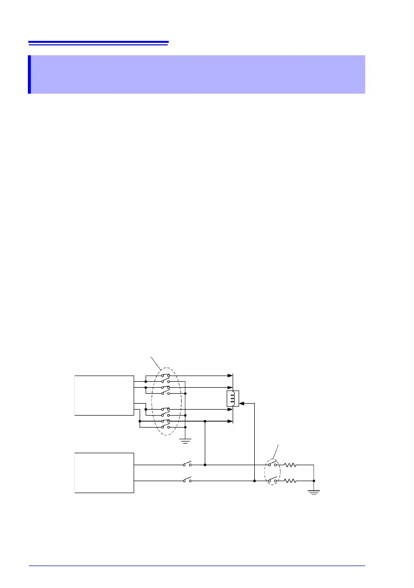
The instrument can also be used in conjunction with a withstanding voltage tester to test
windings. When used with a withstanding voltage tester, the charge stored in the winding
may flow into the instrument at the moment it is connected, damaging it. When using the
instrument in this manner, take the following into account during the production line design
process:
(1) Ensure the contact withstanding voltage of the relays used for switching has a sufficient
safety margin relative to the withstanding test voltage (at a minimum, it should be twice
the peak voltage).
Example high-voltage relays
Okita Works LRL-101-50PC (5 kV DC between contacts)
LRL-101-100PC (10 kV DC between contacts)
Sanyu Switch USM-11524 (5 kV DC between contacts)
USM-13624SB (10 kV DC between contacts)
(2) During withstanding voltage testing, ground all of the instrument’s terminals.
(3) Perform resistance measurement first and the withstanding voltage test last.
If you must perform the withstanding voltage test before resistance measurement, ground
both of the measurement target’s terminals after the withstanding voltage test to discharge
any charge accumulated during the test. Then perform resistance measurement.
Appendix 12 Using the Instrument with a
Withstanding Voltage Tester
Ground measurement terminals
when not performing resistance measurement.
Instrument
Withstanding
voltage tester
Discharge residual
charge.
Measurement target
Use only high-voltage relays.
Using the instrument with a withstanding voltage tester