8.1 External Input/Output Connector and Signals
95
8
JUDGE mode and BCD mode
Output signals operate under either JUDGE mode or BCD mode. In BCD mode, signals are
used for both the upper and lower digits (and range information).
See: "Switching Output Modes (JUDGE Mode/ BCD Mode)" (p. 116)
Pin functions in JUDGE mode
Pin functions in BCD mode
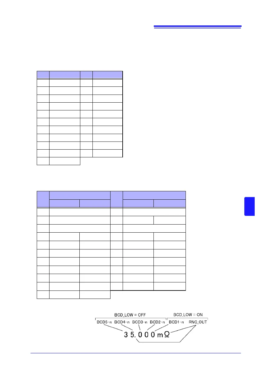
The BCD upper digits and lower digits (and range information) are switched using the
BCD_LOW signal.
Relation between BCD signals and display
Pin Function Pin Function
9 ISO_COM 28 EOM
10 ERR 29 INDEX
11 HI 30 IN
12 LO 31
−
13 − 32 −
14 − 33 −
15 − 34 −
16 − 35 −
17 − 36 −
18 OUT0 37 OUT1
19 OUT2
Pin
BCD_LOW (2pin)
Pin
BCD_LOW (2pin)
OFF ON OFF ON
9ISO_COM28 EOM
10 ERR 29 BCD2-0 RNG_OUT0
11 HILO 30 IN
12 BCD2-1 RNG_OUT1 31 BCD2-2 RNG_OUT2
13 BCD2-3 RNG_OUT3 32 BCD3-0
−
14 BCD3-1 − 33 BCD3-2 −
15 BCD3-3 − 34 BCD4-0 −
16 BCD4-1 − 35 BCD4-2 −
17 BCD4-3 − 36 BCD5-0 BCD1-0
18 BCD5-1 BCD1-1 37 BCD5-2 BCD1-2
19 BCD5-3 BCD1-3