Appendix 5 Effect of Thermal EMF
A7
Appendix
1. Increasing the detection voltage by increasing the measurement current
In the above thermal EMF example, assume that the measurement current is increased
from 100 mA to 1 A. The error will be reduced to 1%.
However, it is important to note that RI
2
power is applied.
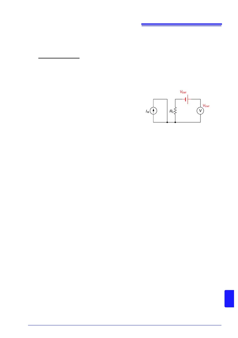
2. Using zero adjustment to cancel thermal EMF
If current is blocked from being applied to
measurement target R
X
, the voltmeter will
only be supplied with thermal EMF V
EMF
.
However, if the SOURCE terminals are
made open-circuit, a current fault will be
detected and a measured value will not be
displayed. Thus, thermal EMF can be
canceled by shorting the SOURCE lines to
block current flow to R
X
and performing zero
adjustment. (Fig. 3).
See: "3.4 Checking Measured Values" (p.35)
See: "Appendix 6 Zero Adjustment" (p.A8)
3. Changing the detection signal to AC
Changing the detection signal to AC is a fundamental solution. Both the thermal EMF
and voltmeter offset voltage can be treated as stable DC voltages as they are viewed for
a short period of time in seconds. This allows frequency domain separation by changing
the detection signal to AC. Resistance meters with offset voltage compensation (OVC)
functionality, including the RM3542, RM3543, and RM3548, can eliminate thermal EMF
by treating the current as a pulse waveform.
1 m × 1 A + 10 V
1 A
=1.01 m
Figure 3. Using zero adjustment to
block current flow to R
X