16
3. OPERATING PROCEDURE [How to Use the Liquid Crystal Display (LCD)]
3.3.2 Monitoring Displays
(10)
(11)
㻞㻜㻝㻞䠋㻜㻥䠋㻜㻝 㻝㻥䠖㻜㻞
㻼㻾㻱㻿㻿㼁㻾㻱
㻵㻺㼀㻿㼀㻳䠊㻼䠖 㻌㻌 㻞㻥㼜㼟㼕
䠆
㻻㻵㻸㻌㻼㻾㻱㻿䠖 㻌㻌 㻝㻡㼜㼟 㼕
㻯㻸㼀䠊㻼㻾㻱㻿䠖 㻖䠊㻖 㻖 㼜㼟 㼕
㼀㻱㻹㻼㻱㻾㻭㼀㼁㻾㻱
㻰㻵㻿䠊㼀㻱㻹㻼㻝䠖 㻟㻞㻜䉣
㻰㻵㻿䠊㼀㻱㻹㻼㻞䠖 㻟
㻝
㻟㻤䉣
㻻㻵㻸㻌㼀㻱㻹㻼䠖 㻟㻣䉣
㻯㻸㼀䠊㼀㻱㻹㻼䠖 㻖㻖㻖䉣
㻞㻺㻰㻌㻿㼁㻯㼀䠊㼀䠊䠖 㻜㻤䉣
㻹㻭 㻵 㻺㼀㻱㻺㻭㻺㻯㻱
㻴㻾䠊㼀㻻㻌㻹㻭㻵㻺㼀䠖 㻜㻜㻜㻜䡄
㻺㻱㼄㼀㻌 㻹㻭 㻵 㻺㼀䠖 㻖 㻖 㻖 㻖
㻝
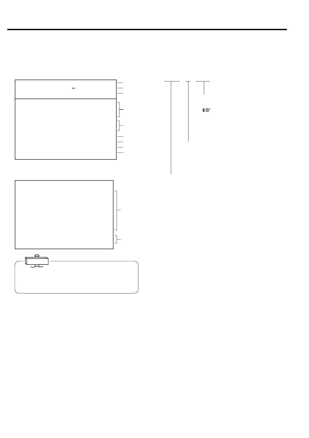
■ Monitor Displays during Normal Operation
Monitor Display 1
Monitor Display 2
“CURRENT” reading is an approximate S-phase Amp
reading.
“OUTPUT” reading is an approximate calculated power
reading.
IMPORTANT
(1) Indicates current time. An asterisk blinks.
(2) Indicates the control state.
(3) Indicates a discharge pressure (DIS.PRESS)
(4) Indicates total running hours (RUN HOUR), total
loaded hours (LOAD HOUR), and total number of
loads (LOAD TIMES).
Blinking asterisk means counting the running
hours.
(5) Indicates a percentage of load to unload of the DSP
air compressor (LOAD RATE).
For Vtype, the rate is calculated based on only
frequency. Indicates “***”, if PQ wide mode is
selected.
(6) Indicates the amperage current of the package
input (CURRENT).
(7) Indicates the operating frequency of the main motor
(FREQUENCY).
(8) Indicates “***” for this air compressor.
(9) Indicates (MASTER), when the air compressor is
master in lead-lag operation.
(10) Indicates each pressure and temperature. “***”
indicates not in use.
(11) Indicates the number of hours until the next
maintenance service (HR. TO MAINT), and the
next maintenance type (NEXT MAINT).
VSDA * SAVE
Indicates ECOMODE is activated for
fixed speed type.
(
3.4.8)
Displayed when stop is limited for AUTO
operation (Standard: no symbol)
INTE : Indicates fixed speed type used the standard, 2-step
control system.
AUTO : Indicates fixed speed type used the automatic motor
stop/restart capacity control system.
VSDB : Indicates Vtype without the AUTO capacity control.
VSDA : Indicates Vtype with the AUTO capacity control
(standard setting for Vtype).
EXIT : Indicated the external capacity control is used.
MR : Indicates multi unit control system through the
communication is used
(1)
(2)
(3)
(4)
(5)
(6)
(7)
(8)
(9)
㻞㻜㻝㻞䠋㻜㻥䠋㻜㻝 㻝㻥䠖㻜㻞
㼀㼅㻼㻱䠖㼂㻿㻰㻭
㻰㻵㻿䠊㻼㻾㻱㻿㻿䠖 㻢㻣㼜㼟㼕
㻖
㻖
㻾㼁㻺 㻌㻴㻻㼁㻾䠖 㻝㻞㻜䡄
㻸㻻㻭㻰 㻌 㻴㻻㼁㻾䠖 㻡 㻠䡄
㻸㻻㻭㻰 㼀㻵㻹㻱㻿䠖 㻝㻞㻟
㻸㻻㻭㻰 㻾㻭㼀㻱 䠖 㻝 㻝䠂
㻸㻻㻭㻰 㼀 㻵 㻹㻱䠖 㻞 㻠䡏
㼁㻺㻸㻻㻭㻰 㻌 㼀 㻵 㻹㻱 䠖 㻝䡏
㻯㼁㻾㻾㻱㻺㼀䠖 㻡 㻜䠝
㻲㻾㻱㻽㼁㻱㻺㻯㼅䠖 㻞㻟 㻚 㻤䠤䡖
㻻㼁㼀㻼㼁㼀 䠖 㻝 㻠 㻚 㻣 䡇
㻹㻭㻿 㼀㻱 㻾
㼃
 Loading...