10 Troubleshooting
Initial troubleshooting
SMGB0136 rev.0 - 07/2021
225
10
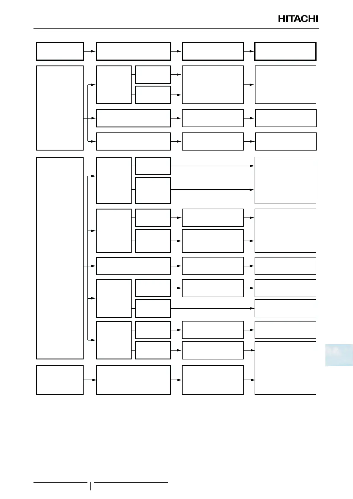
Phenomenon
Indoor Fan Speed is
Not Changed
No Defrosting Operation
Mode is Available during
Heating Operation or
Defrosting Operation is
Continued
“RUN” Indicator or LCD
indication on Remote
Control Switch are
Kept ON
Failure of PCB in Indoor Unit or
Remote Control Switch
Check PCB in indoor / outdoor
unit PCB1 check mode (**), or
check wired controller in self-
checking mode
Check it in indoor / outdoor unit
PCB check mode (**)
Check it by self-checking from
remote control switch
Check thermistor in check mode
of remote control switch (*)
Replace or correctly connect
wiring when it is abnormal
Replace if failed
Replace if failed
Replace or connect correctly
when it is abnormal
Replace reversing valve
Correctly connect wiring
Correctly connect wiring
Correctly connect wiring
Replace it when check mode is
not available
Replace if failed
Cause
Failure of
Discharge Air
Temperature
Thermistor
Failure of
Thermistor
Disconnected
Wire of
Thermistor
Failure of Remote Control Switch
Failure of PCB for Indoor Unit
Failure of
thermistor
for outdoor
evaporating
temperature
during heating
or thermistor
for outdoor
temperature
Failure of
Reversing Valve
Failure of
Outdoor Unit
PCB
Failure of Indoor
Unit PCB
Disconnected Control Wires between
Indoor Unit and Outdoor Unit
Failure of
Thermistor
Disconnected
Wire of
Thermistor
Disconnected
Reversing Valve
Coil
Disconnected
Wires to PCB
Failure of PCB
Disconnected
Wires to PCB
Incorrect
Activation of
Reversing Valve
Measure resistance of coil
Enforced power supply
Check connectors
Check connectors
Check connectors
Check Item
Action (Turn OFF
Main Switch)
Check it by self-checking from
remote control switch (**)
Failure of PCB
? NOTE
• (*): Refer to the item “10.1.2.2 Checking by 7-segment display” in this chapter.
• (**): Refer to the item “10.4.2 RSW, DSWs and LEDs functions RAS-(4-6)HV(R/N)(C/P)2E” or “10.4.3 RSW, DSWs and LEDs func-
tions RAS-(4-6)H(R/N)(C/P)2E” in this chapter.
 Loading...


