10 Troubleshooting
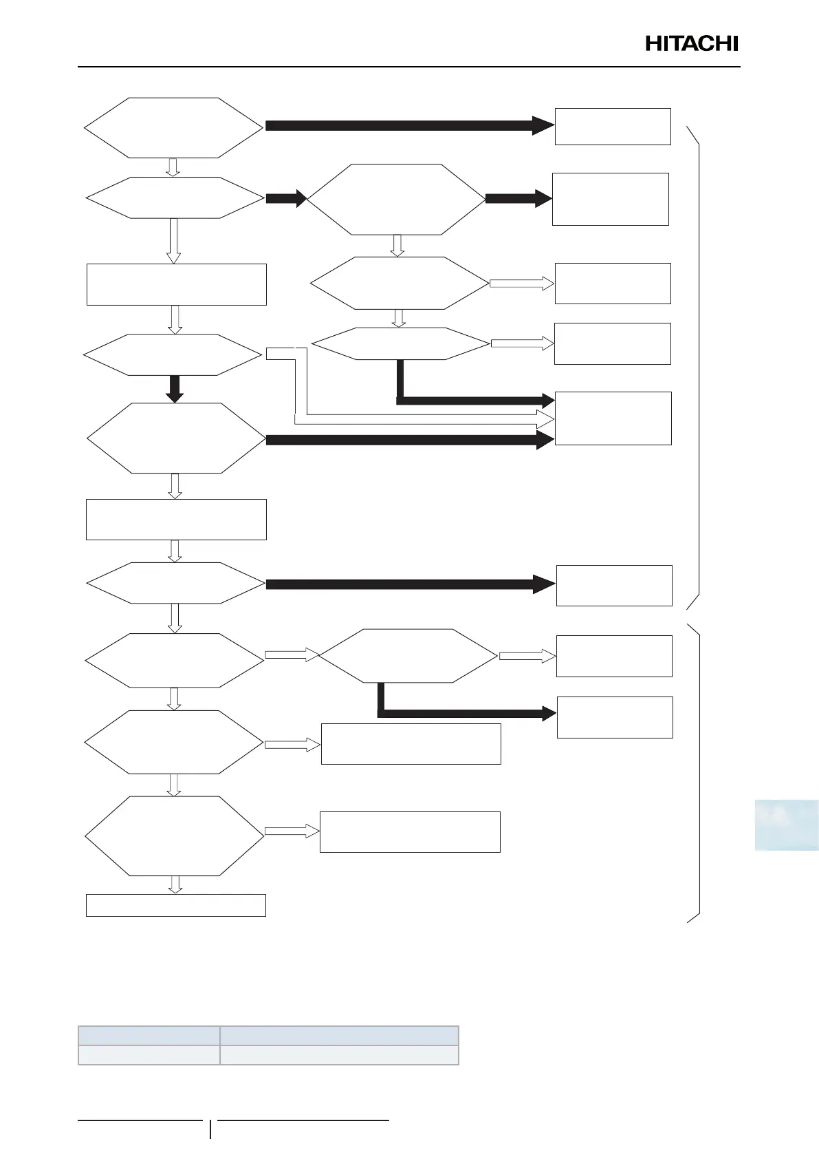
Troubleshooting procedure
SMGB0136 rev.0 - 07/2021
239
10
Set it correctly
No
No
No
Yes
No
Yes
Yes
Yes
No
Yes
Yes
No
Check the fuses of the
outdoor unit power
supply
Yes
Plug PCN2 and CN11
correctly
No
Yes
Yes
No
Outdoor unit
Indoor unit
Remove CN8 of PCB1
Connect CN8 of PCB1
Faulty PCB1
Set correctly
Check the wiring between the
outdoor unit and the indoor unit or
the fuse (EF1) for PCB1
Check other indoor
units
Faulty PCB1
Set correctly
Faulty PCB1
Replace the fuse
Yes
Yes
*1)
Is DSW5-1P (terminal
resistance on PCB1) ON?
Is LED1 (red) on
PCB1 ON?
Is LED2 (green)
on PCB1 ON?
Is LED3 (yellow)
onPCB1ickering
more than once in 10
seconds?
Is PCB1’ setting
non-pole operating?
Is LED5 (yellow) on
PCB1’ ON?
Is LED5 (yellow) on
PCB1’ickeringmorethan
once in 10 seconds?
Does the
refrigeration
system setting between
DSW4+RSW1 on PCB1
and RSW1+RSW2 on
PCB1’ match?
Is LED5 (yellow) ON,
even if PCN1 of PCB1’ is
removed?
Is the voltage
between the terminal
“1” and “3” of PCB1 220V
or 240V? *2)
Is connector (PCN2,
CN1) for the transformer
loosened?
Is the fuse for
PCB1 blown out?
PCB1: Outdoor unit printed circuit board
PCB1’: Indoor unit printed circuit board
*1) In case that terminal resistance (DSW5-1P) is OFF when H-LINK II connection is performed.
• Set the terminal resistance to ON when CN8 is removed.
• Set the terminal resistance to OFF when CN8 is reconnected.
*2) Check item
Power supply Faston terminal
1~ 230V 50Hz Between 1 and 3 of PCN1 on OU PCB