10 Troubleshooting
Troubleshooting in check mode
SMGB0136 rev.0 - 07/2021
297
10
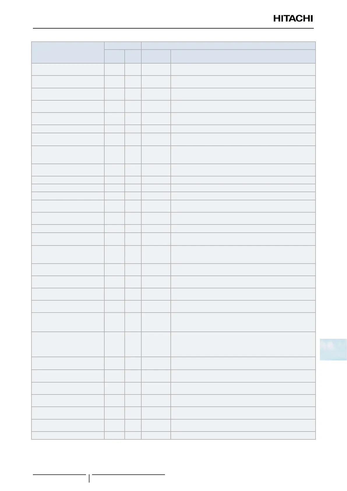
Item
Item Indication data
Check
number
Indic. Indic. Contents
Input/output state of outdoor
micro-computer
01
SC 3
Indicates only for the segments corresponding to the equipment in
thegure.(Seegureabove)
Capacity of operating indoor unit 02
oP 36
00~199
Incasethatcapacityishigherthan100,thelasttwodigitsash
Control software number 03
SP 12↔34.
Control Software No. in use is indicated. Alternately upper 2 digits
and lower 2 digits are indicated every 0.5 sec.
Inverter software number 04
iP 12↔34.
Inverter Software No. in use is indicated. Alternately upper 2 digits
and lower 2 digits are indicated every 0.5 sec.
Inverter order frequency to
compressor
05
HI 74
0~115 ( Hz)
Incasethatfrequencyishigherthan100Hz,thelasttwodigitsash.
Airowstep 06
Fo 15
00~15 step
Outdoor unit expansion valve
opening
07
Eo 30
00~100 (%)
In case that expansion valve opening is 100%, “00”ashes
Temperature at the top of
compressor
10
d 94
00~142 (ºC)
In case that temperature is higher than 100ºC, the last two digits
ash
Evaporating temperature at
heating
11
E 34
-19~80ºC
Ambient air temperature 12
o 44
-19~80ºC
Condenser Pipe Temperature 13
C 22
-19~80ºC
Control information 14
F 20
Internal information of the PCB
Inverter Firstly Current 15
A1 12
00~199 (A)
Incasethatcurrentishigherthan100ºC,thelasttwodigitsash
Inverter secondary current 16
A2 20
00~199 (A)
Incasethatcurrentishigherthan100ºC,thelasttwodigitsash
Indoor unit address 17
nA 00
00~63
Indoor unit expansion valve
opening
18
EA 20
00~100 (%)
In case that opening is 100%. “00”ashes
Liquid pipe temperature of indoor
unit
(freeze protection)
19
LA 05
-19~127 (ºC)
WhenTemp.ishigherthan100,thelasttwodigiteash.
Gas Pipe Temperature of Indoor
Unit
20
uA 26
-19~127 (ºC)
WhenTemp.ishigherthan100,thelasttwodigiteash.
Indoor unit inlet air temperature 21
iA 28
-19~127 (ºC)
WhenTemp.ishigherthan100,thelasttwodigiteash.
Indoor unit outlet air temperature 22
oA 20
-19~127 (ºC)
WhenTemp.ishigherthan100,thelasttwodigiteash.
Cause of indoor unit stoppage 23
dA 01
00~99
Indicated Cause of Stoppage Code
Total accumulated operation
time of
Compressor
24
UJ 00↔00
0 to 9999 (x 10 hours)
Alternately upper 2 digits and lower 2 digits are indicated every 0.5
sec.
Accumulated operation time
of compressor (can be reset
to zero for instance when
compressor is replaced)
25
cU 00↔00
0 to 9999 (x 10 hours)
Alternately upper 2 digits and lower 2 digits are indicated every 0.5
sec.
Outdoor unit alarm code 26
AC 08
00~99
Indicated Alarm Code
Cause of stoppage at inverter 27
i 1
00~99
Indicated Cause of Stoppage Code
Cause of FAN stoppage 28
F 0
00~99
Indicated Cause of Stoppage Code
Abnormal data record 29
n1 00
One of the abnormal data record from latest (n1) to oldest (n9) is
indicated. Alarm code or cause code is indicated.
Total capacity of indoor unit
connected
30
CP 36
00~199
Incasethatcapacityishigherthan100,thelasttwodigitsash
Quantity of connected indoor
units
31
AA 2
00~64
Refrigerant address 32
GA 0
00~63
 Loading...


