10 Troubleshooting
Checking procedure for main parts
SMGB0136 rev.0 - 07/2021
318
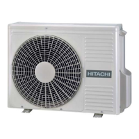
Inverter printed circuit board for control: PCB2
DSW1
DSW2
DSW3
DSW4
DSW6
DSW7
RSW1
PSW1
PSW2
PSW3
SEG1
TP1
No. DIP Switch Code Denition No. DIP Switch Code Denition
1 DSW1 Test Run 7 PSW1 Manual Defrosting
2 DSW2 Function Setting 8 PSW2
Decrease (▼)
3 DSW3 Model Setting 9 PSW3
Increase (▲)
4 DSW4 System Address Setting: Double Digit 10 RDW1 System Address Setting: Single Digit
5 DSW6 Function Setting 11 SEG1 7-segment Display
6 DSW7 Function Setting 12 TP1 Test Port for Factory
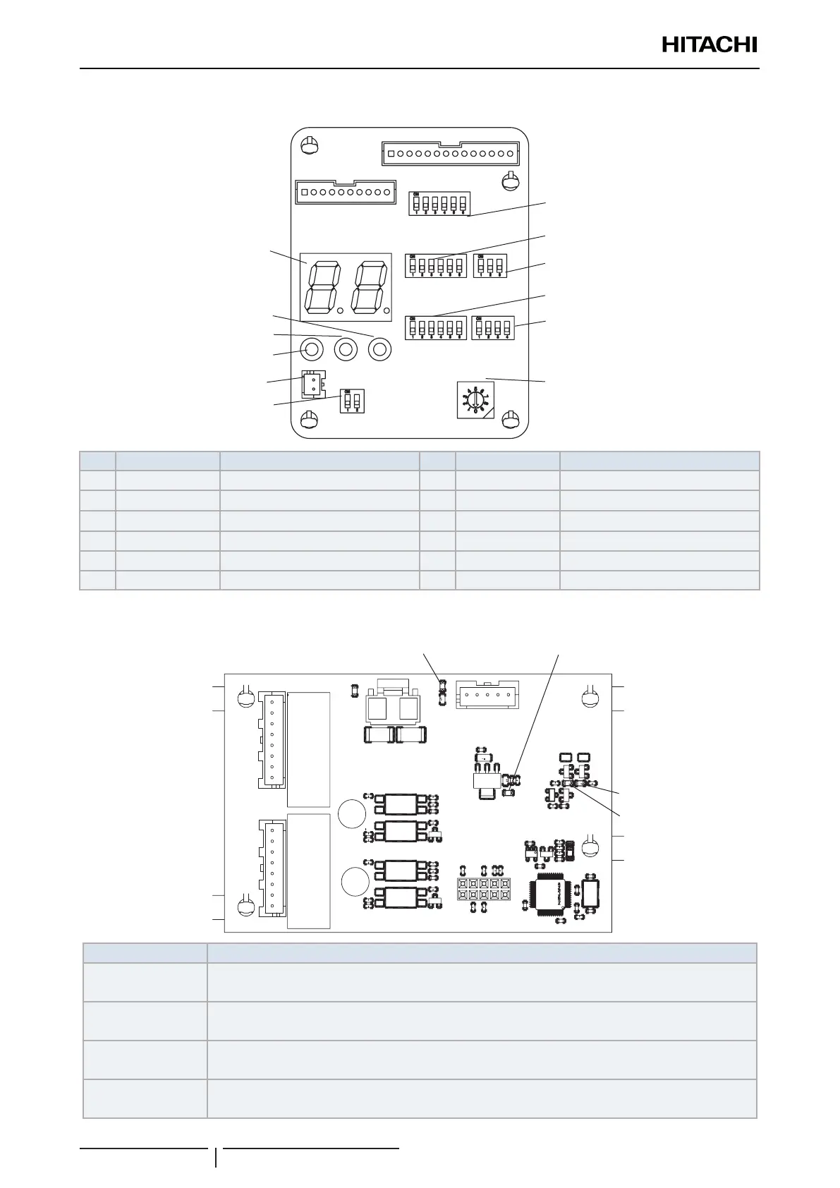
Printed Circuit Board for Fan Control: PCB3
LED1
LED2
LED3LED4
Part name Contents of functions
LED1 (Yellow)
Communication Indicator.
Normal condition: Activated / ON. Abnormal condition: Deactivated / OFF.
LED2 (Red)
Communication Indicator.
Normal condition: Activated / ON. Abnormal condition: Deactivated / OFF.
LED3 (Green)
Power source indicator for Fan PCB (3.3V).
Normal condition: Activated / ON. Abnormal condition: Deactivated / OFF.
LED4 (Green)
Power source indicator for Fan (15V).
Normal condition: Activated / ON. Abnormal condition: Deactivated / OFF.