11 Maintenance notes
Service and maintenance record using the 7-segment display
SMGB0136 rev.0 - 07/2021
329
11
RAS-(4-6)(V)(R/N)(C/P)2E
Customer’s name: ______________________________ Date: _______________________
Outdoor unit model
(Serial number: _________________)
RAS-
(Serial number: ______________)
RAS-
(Serial number: ______________)
1. Operation mode
2. Test Run Start Time
3. Data Collect Start Time
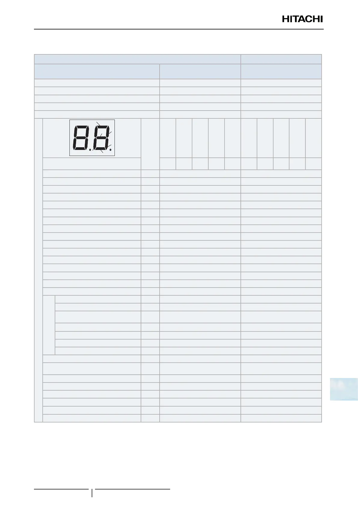
4. Read Out Data from 7-Segment in Outdoor Unit
5. Protection Control Code
Checking Mode
YCH
(CH)
Y21
(RVR)
Y20A
(SVA)
Y20F
(SVF)
FAN1
FAN2
SC
Y20A
(SVA)
Y21
(RVR)
Y52C
(CMC)
Fan
YCH
(CH)
Y20A
(SVA)
Y21
(RVR)
Y52C
(CMC)
Fan
YCH
(CH)
Input/Output State of Outdoor
Micro-Computer
Total Capacity of Operating Indoor Unit
oP
Control Software No
SP
Inverter Software No.
iP
Inverter Order Frequency to Compressor
H1
Outdoor Fan Step
Fo
Outdoor Fan Speed
F5.
Outdoor Expansion Valve Opening
Eo
High Pressure (Discharge Pressure)
Pd.
Low Pressure (Suction Pressure)
Ps.
Discharge Temperature
d
Evaporating Temperature
E
Ambient Air Temperature
o
Outdoor Condensing Temperature
C
Inverter Fin Temperature
F
Inverter Primary Current
A1
Inverter Secondary Current
A2
Checking for Indoor Unit
Indoor Unit Address
n-
Indoor Expansion Valve Opening
E-
Liquid Pipe Temperature of Indoor Unit
L-
Gas Pipe Temperature of Indoor Unit
u-
Indoor Unit Inlet Air Temperature
i-
Indoor Unit Outlet Air Temperature
o-
Cause Code of Indoor Unit Stoppage
d-
Accumulated operation time of the unit
UJ
Accumulated operation time of Compressor
(After Reset)
cU
Outdoor Unit Alarm Code
AC
Cause Code of Inverter Stoppage
i
Capacity of Indoor Unit(capacity DIP)
oC
Total connection capacity of the indoor unit*
CP
Quantity of indoor units connected
AA
Refrigeration system address
GA
? NOTE
• O.U.: Outdoor Unit.
• I.U.: Indoor unit.
• FAN: Constant speed fan.
• 52C: CMC.
• PSH: High pressure switch.
• 20A: Solenoid valve (SVA).
• 20F: Solenoid valve (SFV).
• 21: Reversing valve (RVR).
• CH: Oil heater.
• *: Multiply 1/8 by the code on the 7-segment.