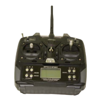
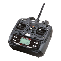
7 Channel 2.4 GHz Aircraft Computer Radio System
7 Channel 2.4 GHz Aircraft Computer Radio System
13
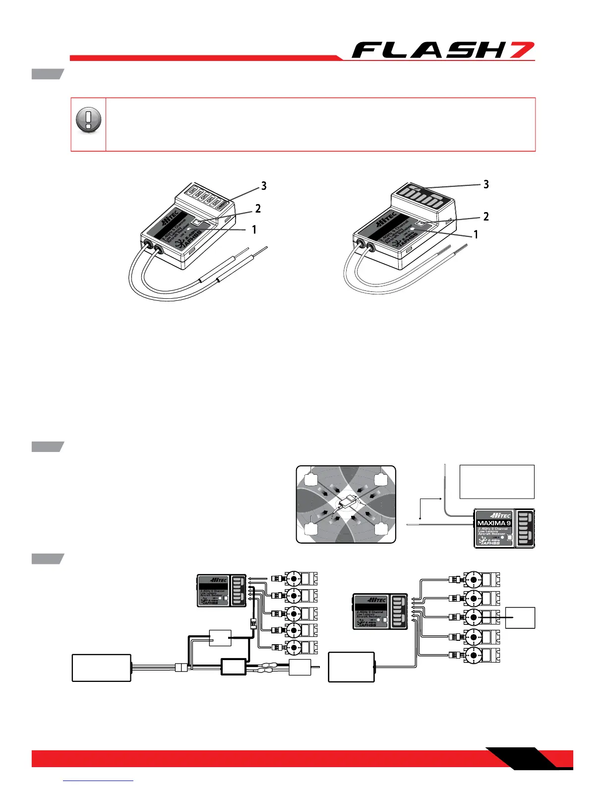
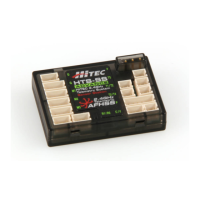
1. Function Button: Used for binding the receiver to the Flash 7 and entering the FAIL-SAFE or Hold
feature.
2. Dual LED Status Indicator: Indicates the set-up process codes and current status of the receiver.
3. Channel Output and Battery Input Ports: The ports for battery power input and servos, gyros and
other accessories’ output ports are located at the side end of the Maxima receivers.
4. Low Battery Warning: If the receiver’s battery levels fall below 3.6V, the RED LED will ash.
5. FAIL-SAFE/Hold Mode Selectable: Servos and other accessories position can be set with a FAIL-SAFE
point if power to the receiver is lost.
Maxima Series Receivers
MA XIMA
6
MA XIMA
9
C
H
1
C
H
2
C
H
3
C
H
4
C
H
5
C
H
6
C
H
7
CH8
BAT/9
MAXIMA 6 MAXIMA 9
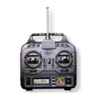
Maxima Series Receiver Antenna Installation
The Maxima receiver series antenna system was
created to provide the optimum signal capture
capability. Our two antennas must be installed
properly. Refer to the illustration below.
RX
90˚
Recommended installation
method to optimize
receiver performance
CH1
CH2
CH3
CH4
CH5
CH6
CH7
CH8 BAT/9
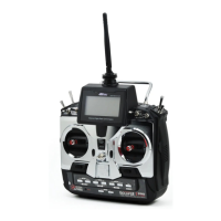
Electric powered aircraft with Electronic Speed Control
Use this method on electric planes using ESCs
providing power to the receiver and servo functions.
Maxima Series Receiver Connection Diagrams
CH1
CH2
CH3
CH4
CH5
CH6
CH7
CH8
BAT/9
SERVO
SERVOS ERVO SERVO
Power Battery
Motor
SERVO
BEC
ESC
Glow, gas or electric powered aircraft using a
separate receiver battery supply.
Follow this connection diagram when using a
regulated Li-Po, or 4.8 to 6V receiver battery.
CH1
CH2
CH3
CH4
CH5
CH6
CH7
CH8 BAT/9
SERVOSERVO SERVO SERVO
Receiver
Battery
SERVO
Engine
The Maxima series is designed for use with G2 AFHSS radios such as the Aurora 9X and Flash
series. USE ONLY Digital SERVOS with the Maxima receivers. Analog servos cannot be used with
the Maxima series receivers.
arning
Note
TipTip
Tip
Caution