Vibration testing and balancing device - Setup instructions EasyBalancer EB 3500
3 - 10
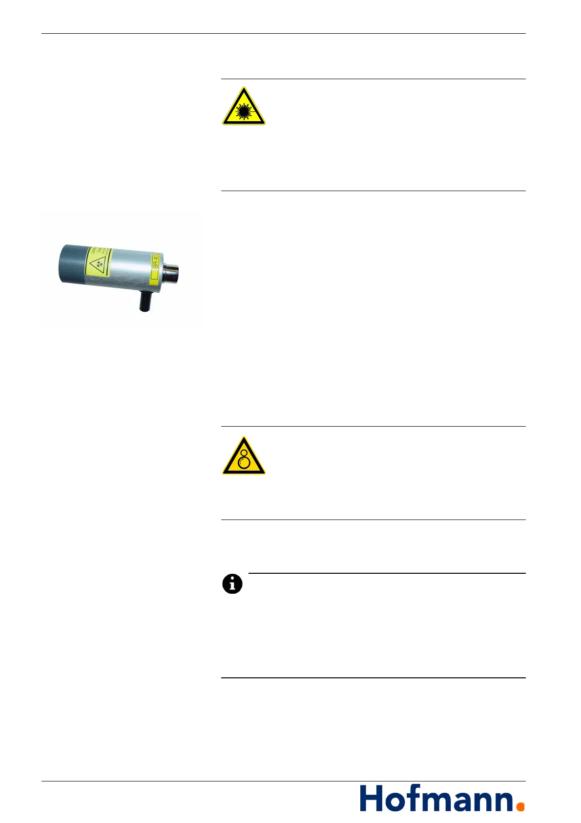
3.7.3 Laser speed sensor (optional)
A laser speed sensor can be used
for scanning markings that are very close together,
for scanning from a very large distance or through a pane
of glass,
under strong fluctuating light (fluorescent tubes).
When using a reflective tape, the beam does not need to be
aligned very precisely.
When scanning a shiny surface with a dark marking, the laser
beam must strike the surface as perpendicularly as possible.
The scanning head must be kept still when scanning from a great
distance. To do this, it can be clamped in the magnetic stand us-
ing the pin on the underside.
3.7.3.1 Positioning the speed sensor
Scanning distance: approx. 50 to >2000 mm
Light point: approx. 1.8 x 3.5 mm.
During balancing, the “zero position” from which the angle for un-
balance correction is counted is determined by the position of the
test weight.
During calibration when balancing, the position of the speed sen-
sor must remain unchanged, otherwise an incorrect measure-
ment will be made with reference to the angular position.
Danger from laser beam
Do not look directly into the laser beam.
Do not point it at other persons.
The lens of the probe must not be replaced.
Comply with the hazard class warnings on
the laser speed sensor and do not remove them.
Risk of entanglement or entrapment
When positioning the sensors, make sure
the cables are not caught in or on rotating parts.
Arrange the cables so that they cannot be pulled
in or entangled by rotating parts.