Vibration testing and balancing device - Setup instructions EasyBalancer EB 3500
3 - 8
3.7.2 Speed sensor
The speed sensor is designed as a photo-reflexive probe with
a visible light spot. To record the speed, a speed mark is scanned,
which is attached to the rotating shaft of the machine to be exam-
ined/balanced. In most cases, the reflective tape included in
the scope of delivery is used for this purpose.
The speed mark can also be applied with Tipp-Ex, felt-tip pen
or chalk, for example.
The speed sensor is used to record the speed and as an angular
reference for unbalance measurement and correction. The lead-
ing edge of the marking triggers the speed and angle detection.
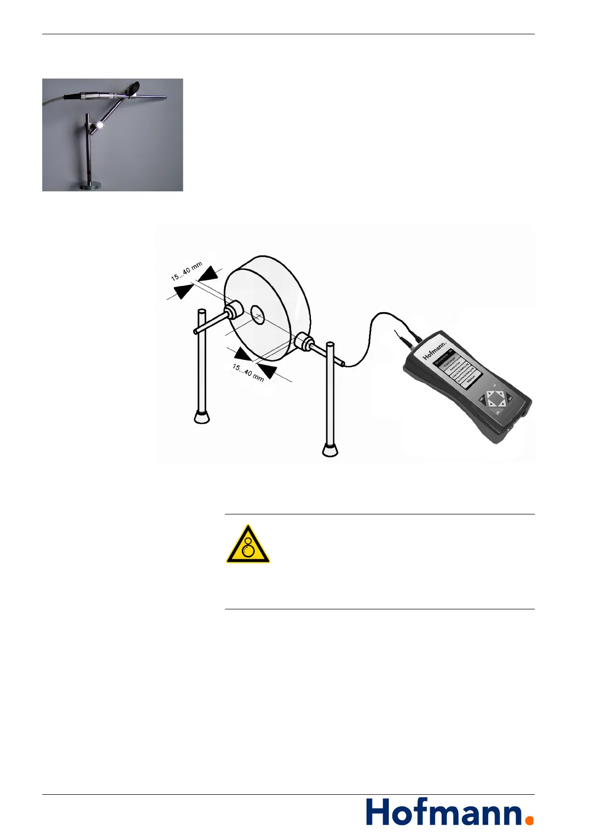
Fig. 3-5: Measurement setup – example with speed sensor
3.7.2.1 Positioning the speed sensor
The distance between the speed sensor and the speed
mark should not be less than 15 mm (up to approx. 100 mm
depending on the light effect).
Align the sensor at a slight angle, not perpendicular to
the scanning surface.
Make sure that the contrast of the speed mark to the rest of
the shaft circumference is sufficiently large to detect
the speed mark.
Risk of entanglement or entrapment
When positioning the sensors, make sure
the cables are not caught in or on rotating parts.
Arrange the cables so that they cannot be pulled
in or entangled by rotating parts.