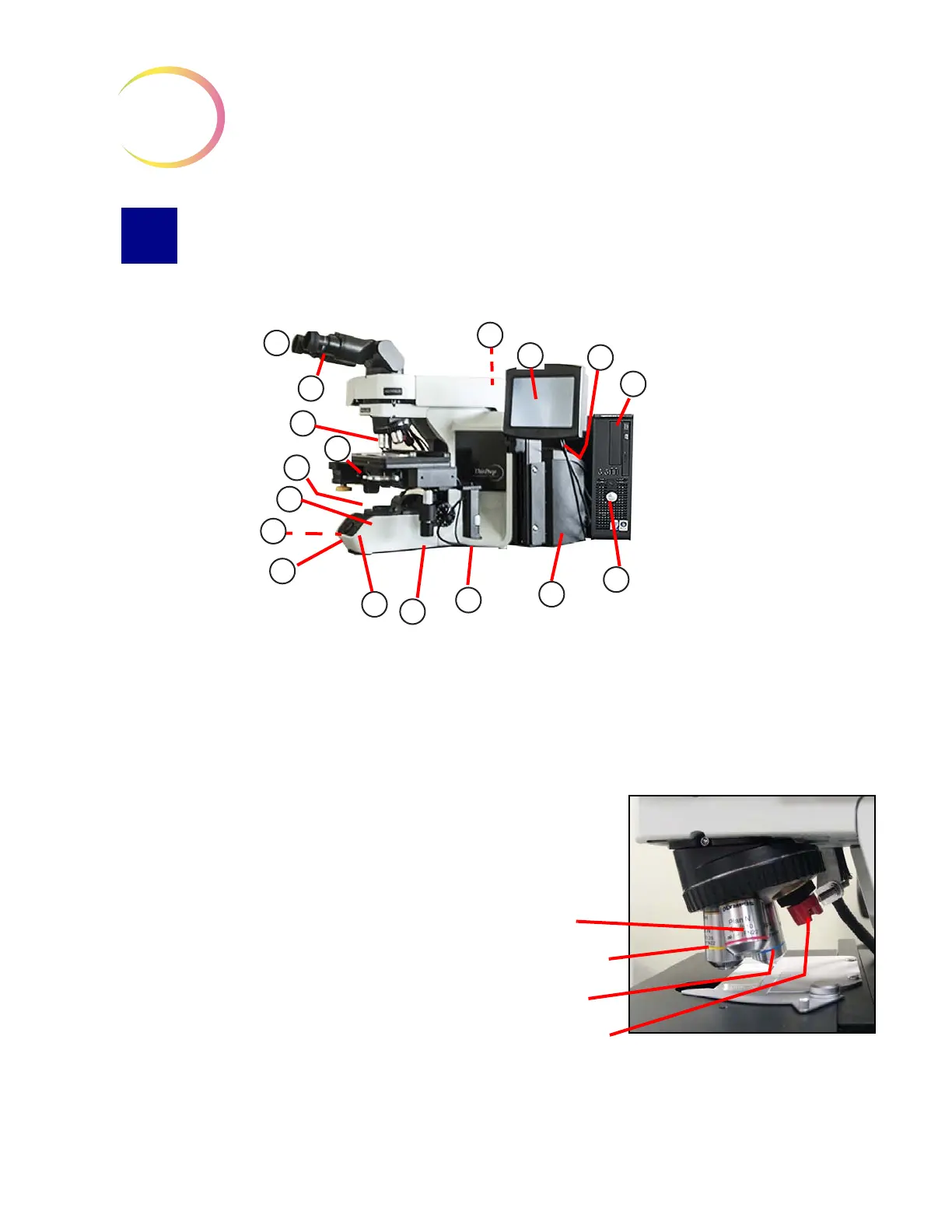
1. Eyepieces
2. Binocular tube
3. Revolving nosepiece (4X, 10X,
40X, plus position sensor)
4. Motorized stage
5. Condenser (under stage)
6. Collector
7. Coarse/fine focus knob (on left
side of microscope)
8. Light intensity adjustment knob
9. X,Y axis stage control knobs
(stage control)
10. Microscope power switch
(on back left of microscope with
black side panel)
11. Allen screwdriver
(near the controller on the back of
the microscope with the black
side panel)
12. Computer
13. Touch screen interface
14. Computer power switch
15. Controller
16. Review control
17.
Note:
The “SET” button is not
used.
The “LIM” button is also
not used and will
illuminate, with no effect, if
pushed.
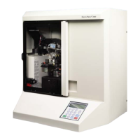
Revolving nosepiece
4X objective (red stripe)
10X objective (yellow stripe)
40X objective (blue stripe)
10X objective position sensor