CIPer
TM
MODEL 50 CONTROLLER – INSTALLATION AND COMMISSIONING INSTRUCTIONS
Wiring Terminals
The CIPer Model 50 is equipped with push-in terminal plugs.
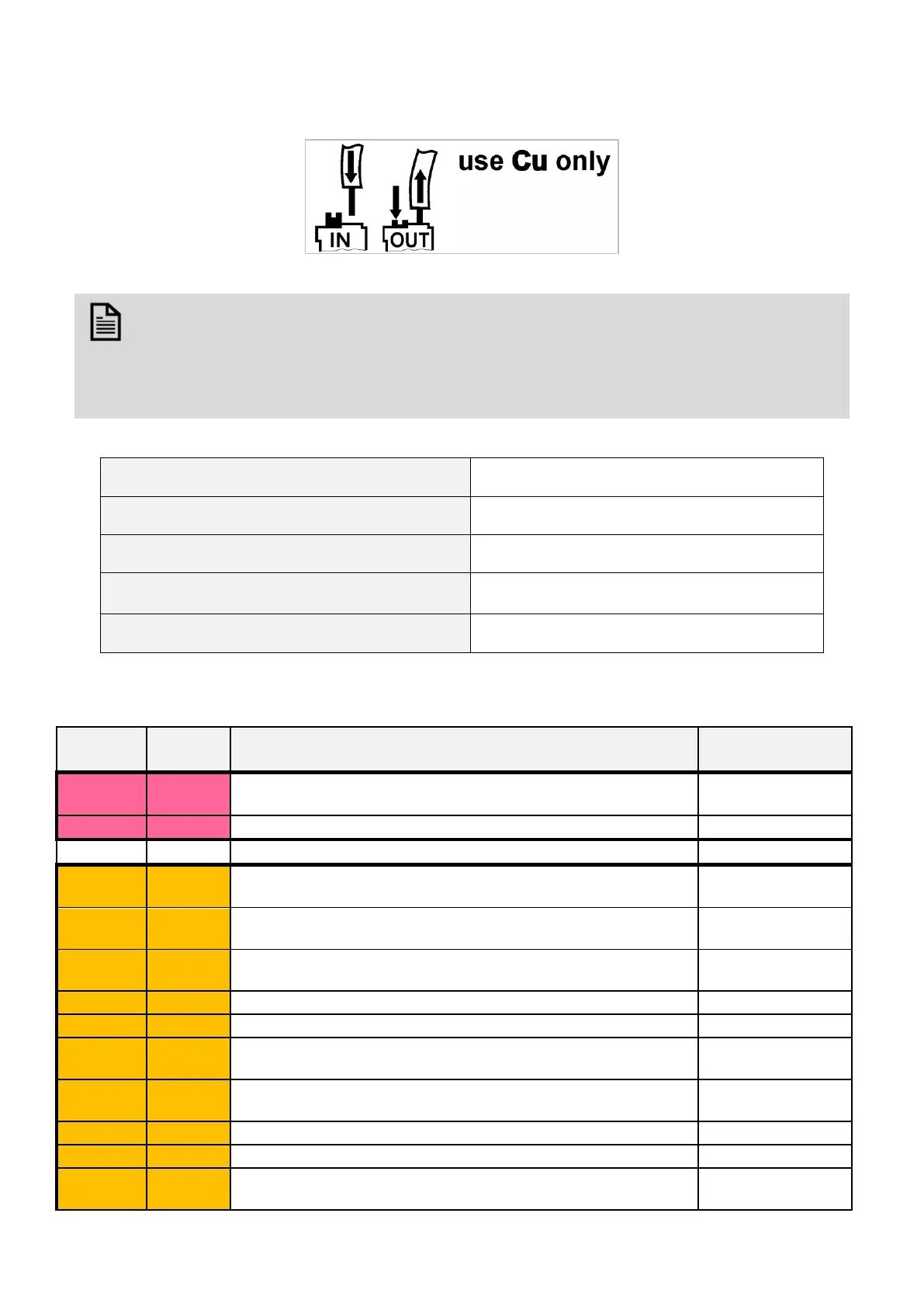
Figure 23: Inserting/removing wires from push-in terminals
NOTE
• With solid conductors, ferrules are prohibited.
• Use only one conductor per push-in terminal.
• If, nevertheless, two stranded wires are to be connected to a single push-in terminal, twin wire
end ferrules must be used.
Table 7. CIPer Model 50 push-in terminal wiring specifications
0.0003… 0.002” (0.2 … 1.50 mm)
Solid conductor H05(07) V-K
0.0003… 0.002” (0.2 … 1.50 mm)
Stranded conductor H05(07) V-K
0.0003… 0.002” (0.2 … 1.50 mm)
Stranded conductor with wire end ferrules (w/o
plastic collar)
0.0003… 0.002” (0.2 … 1.50 mm)
0.4” + 0.04” (10.0 +1.0 mm)
Terminal Assignment
Table 8. Terminal assignment
Supply voltage (GND), int. connected with term. 31 and system
GND (term. 19+37)
Binary output 1. N.O. relay contact switching input power
connected to terminal 8
Binary output 2. N.O. relay contact switching input power
connected to terminal 8
Binary output 3. N.O. relay contact switching input power
connected to terminal 8
Common relay contact for BO1, BO2, and BO3
Binary output 4. N.O. relay contact switching input power
connected to terminal 9
Binary output 5. N.O. relay contact switching input power
connected to terminal 12
Binary output 6. N.O. relay contact switching input power
connected to terminal 13

 Loading...


