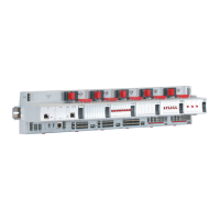
CIPer
TM
MODEL 50 CONTROLLER – INSTALLATION AND COMMISSIONING INSTRUCTIONS
To ensure that the discovery of devices, datapoints, schedules, and histories does not fail, you should enter a
gateway address. If there is no gateway address physically given by the Network Setting, then enter a gateway
address that relates to the IP address of the enabled Ethernet Interface. In Figure 11 the gateway address is
192.168.1.1, hence the IP address of Ethernet adapter 1 must be in the range of 192.168.1.2 to
192.168.1.255.
Default IP Addresses of Ethernet Interfaces 1 and 2
In any case, the default IP address of Ethernet interface 1 is: 192.168.200.20, mask 255.255.255.0
and the default IP address of Ethernet interface 2 is:192.168.201.20, mask 255.255.255.0
LEDs
The CIPer Model 50 controller features the following LEDs:
Figure 12: CIPer Model 50 controller LEDs
Table 4. CIPer Model 50 controller LEDs
Lit = Daemon starting; flashing = station starting; if L2 is also flashing, then the
station has started.
Lit = platform has started / is reachable; flashing = station has started / is
reachable.
RS485-1 status LED indicating transmission of communication signals.
RS485-1 status LED indicating reception of communication signals.
Indicates an active alarm; is controlled by WEBs- Alarm System; is configurable.
See also section "CIPer Model 50 Controller Troubleshooting, Pg. 67 for a detailed description of the
behaviors of the LEDs and their meanings.
RS485 Interfaces
General
The CIPer Model 50 controller features two RS485 interfaces:
RS485-1 (consisting of push-in terminals 24 [GND-1], 25, and 26) is isolated and can be used for any
RS485-based communication protocol available within WEBs- Ecosystems, E.g: Panel Bus, BACnet MS/TP,
etc.
RS485-2 (consisting of push-in terminals 29, 30, and 31 [GND-2]) is non-isolated (i.e. GND-2 is internally
connected with terminal 1 [24V~0]) and can be used for any RS485-based communication protocol available
within WEBs- Ecosystems, e.g.: Panel Bus, BACnet MS/TP, etc.
NOTE
It is imperative that the RS485-2 be powered by a power supply having the proper polarity. Failure to do so
will make data transmission impossible.

 Loading...
