NOTE
With regards to Figure 50 and Figure 51, please note the following:
• Always power each CIPer Model 50 controller and the connected BACnet MS/TP modules
via separate transformers.
• For "L," see section "RS485 Standard".
• If any of the devices are electrically isolated, it is recommended that those devices be
connected to signal ground. See section "RS485 Standard".
• Between devices equipped with non-isolated RS485 bus interfaces, potential differences
of max. ±7 V are allowed. Further, this bus should not extend beyond a single building.
Example 1: Single CIPer Model 50 Controller and Connected BACnet Modules (with inserted termination
resistor)
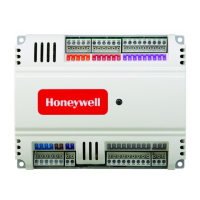
Figure 48: Connection of a single CIPer Model 50 controller via its RS485-2 interface to a BACnet MS/TP
Bus
The termination resistor must be inserted directly into the terminals of the last BACnet MS/TP module.
Example 2: Multiple CIPer Model 50 Controllers and Connected BACnet Modules
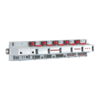
Figure 49: Connection of multiple CIPer Model 50 controllers via their RS485-2 interfaces to a BACnet
MS/TP Bus

 Loading...
