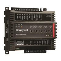
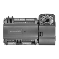
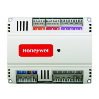
CIPer
TM
MODEL 50 CONTROLLER – INSTALLATION AND COMMISSIONING INSTRUCTIONS
`
Figure 29: WEB-EHSERIESNX26X connection example (with two XS830 Auxiliary Terminal Packages)
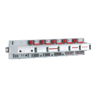
The XS830 and XS831 Auxiliary Terminal Packages are optional accessories which can be mounted onto the
top and/or bottom of the CIPer Model 50 controller in order to equip them with additional terminals for the
connection of, e.g., shields, sensors, GND, N, 230 V, or 24 V (but not earth).
NOTE
Use a min. distance of 10 cm between power cables and 0…10 V / sensor cables in order to
prevent signal disturbances on the 0…10 V / sensor cables.
Internal I/Os of the CIPer Model 50
Universal Inputs
The WEB-EHSERIESNX26XX is equipped with ten universal inputs (UIs) configurable (in WEBs N4). For
information on the accuracy of the sensor inputs, their differential measurement error, the characteristics
BO1
BO2
BO3
IN
IN4
BO4
BO5
IN5
IN6
BO6
BO7
IN7
IN8
BO8
3 5 6 7 8 9 10 11 12 13 14 15 16 17 18
n.a.
4
AO3
22
AO2
21
AO1
20
GND
19
~
AO4
23
GND1
GND2
485-1+
485-2+
485-1-
485-2-
n.a.
n.a.
n.a.
BI1
BI2
BI3
BI4
UI1
UI9
UI10
UI2
UI3
UI4
UI5
UI6
UI7
24 25 26 27 28 29 30 31 32 33 34 35 36 38 39 40 41 42 43 44 45 46
UI8
47
GND
37
n.a.
XS830
2 3 4 5 6 7
B1 B2 B3 B4 B5 B6 B7
2 3 4 5 6 7
A1 A3 A4 A5 A6 A7
1514
XS830
2 3 4 5 6 7
B1 B2 B3 B4 B5 B6 B7
2 3 4 5 6 7
A1 A3 A4 A5 A6 A7
33
40
24V-0
24V~
1 2
L N
2
1
BLOCK 1 BLOCK 2BLOCK 1 BLOCK 2
WARNING
Risk of electric shock or equipment damage!
Low voltage and line voltage must not be wired
within the same block.
WEB-EHSERIESNX26X
A2
1
1
1 1
A2

 Loading...
