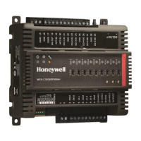
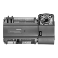
CIPer
TM
MODEL 50 CONTROLLER – INSTALLATION AND COMMISSIONING INSTRUCTIONS
Troubleshooting
CIPer Model 50 Controller Troubleshooting
The following LEDs of the CIPer Model 50 controller can be used for troubleshooting purposes:
• Power LED (green)
• Status LED (red)
• L1 and L2 LEDs (yellow)
• Tx (sending data on RS485-1) and Rx (receiving data on RS485-1) LEDs
Power LED (green) of CIPer Model 50
Table 28. CIPer Model 50 controller power LED
• Check power supply voltage.
• Check wiring.
• If problem persists, replace hardware.
Status LED (red) of CIPer Model 50
Table 29. CIPer Model 50 controller status LED
ON continuously after
power-up
Indicates an active alarm;
is controlled by WEBs-
Alarm System; is
configurable.
• Try powering down and then powering
up the CIPer Model 50 controller.
• If problem persists, replace hardware.

 Loading...
