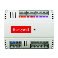
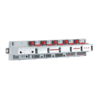
Panel Bus Connection
The CIPer Model 50 controller features two RS485 interfaces to which Panel Bus modules can be connected:
RS485-1 (consisting of push-in terminals 24 [GND-1], 25, and 26) and/or RS485-2 (consisting of push-in
terminals 29, 30, and 31 [GND-2]).
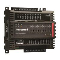
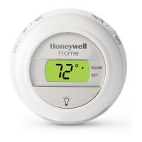
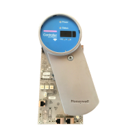
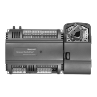
Overview of Panel Bus I/O Modules
Figure 34: Overview of Panel Bus I/O Modules
Panel Bus Considerations
• RS485-1 (isolated)
– Max. Panel Bus length:
o 1200 feet. Any type of cabling and topology (including star and loop topology) possible. No
additional end termination permitted.
o 3600 feet (9.6 – 78.8 kbps) or 2400 feet (115.2 kbps) (see also section "RS485 Standard").
Mandatory twisted-pair or telephone cable and daisy chain topology. The CIPer Model 50
must be positioned at one end of the Panel Bus, and an end termination (120 Ω) at the other
end. Further, the three-position slide switch (see Figure 14) must be set to "END."
• RS485-2 (non-isolated)
– Max. Panel Bus length:
o 1200 feet. Any type of cabling and topology (including star and loop topology) possible. No
additional end termination permitted.
o 3600 feet (9.6 – 78.8 kbps) or 2400 feet (115.2 kbps) (see also section "RS485 Standard").
Mandatory twisted-pair or telephone cable and daisy chain topology. The CIPer Model 50
controller must be positioned at one end of the Panel Bus, and an end termination (120 Ω) at
the other end.
– Must not extend beyond a single building or building floor
• Max. no. of Panel Bus I/O modules per RS485 interface
– Max. no. of Panel Bus I/O modules of a given model: 16
– Total max. no. of Panel Bus I/O modules: 64
• Max. no. of Panel Bus I/O modules per CIPer Model 50
– Max. no. of Panel Bus I/O modules of a given model: 32

 Loading...
