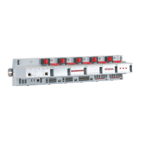
CIPer
TM
MODEL 50 CONTROLLER – INSTALLATION AND COMMISSIONING INSTRUCTIONS
Binary output 7. N.O. relay contact switching input power
connected to terminal 16
Binary output 8. N.O. relay contact switching input power
connected to terminal 17
Ground terminal (see NOTE below)
ref. GND of RS485-1 (isolated)
"+" signal for RS485-1 (isolated)
"-" signal for RS485-1 (isolated)
"+" signal for RS485-2 (non-isolated)
"-" signal for RS485-2 (non-isolated)
ref. GND of RS485-2, int. conn. with 24V-0 (term. 1) and system
GND (term. 19+37)
Binary input 1 (static dry contact) / pulse counter (fast totalizer)
Binary input 2 (static dry contact) / pulse counter (fast totalizer)
Binary input 3 (static dry contact) / pulse counter (fast totalizer)
Binary input 4 (static dry contact) / pulse counter (fast totalizer)
Ground terminal (see NOTE below)
Universal input 9 (for NTC10kΩ / NTC20kΩ / 0...10 V / slow BI)
Universal input 10 (for NTC10kΩ / NTC20kΩ / 0...10 V / slow BI)
Universal input 1 (for NTC10kΩ / NTC20kΩ / 0...10 V / slow BI)
Universal input 2 (for NTC10kΩ / NTC20kΩ / 0...10 V / slow BI)
Universal input 3 (for NTC10kΩ / NTC20kΩ / 0...10 V / slow BI)
Universal input 4 (for NTC10kΩ / NTC20kΩ / 0...10 V / slow BI)
Universal input 5 (for NTC10kΩ / NTC20kΩ / 0...10 V / slow BI)
Universal input 6 (for NTC10kΩ / NTC20kΩ / 0...10 V / slow BI)
Universal input 7 (for NTC10kΩ / NTC20kΩ / 0...10 V / slow BI)
Universal input 8 (for NTC10kΩ / NTC20kΩ / 0...10 V / slow BI)
NOTE
All AOs, UIs, and BIs share the same ground potential. It is thus possible to connect just one combined
GND signal for all AOs, UIs, and BIs. Auxiliary terminals may be used if needed.

 Loading...
