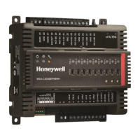
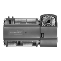
CIPer
TM
MODEL 50 CONTROLLER – INSTALLATION AND COMMISSIONING INSTRUCTIONS
USB 2.0 Device Interface (as Network
Interface)
USB 2.0 Host Interface (max. 200 mA)
RS232 M-Bus communication via 45-feet
(15 m)-long PW3 / PW20 / PW60
converters
Status LED (red; indicates an active alarm;
is controlled by Niagara Alarm System; is
configurable)
LED L1 (yellow; lit = Daemon starting;
flashing = station starting; if L2 is also
flashing, then the station has started)
LED L2 (yellow; lit = platform has started /
is reachable; flashing = station has started
/ is reachable)
Bus status LEDs (for isolated RS485-1
interface)
1)
Depending upon bit rate. However, in the case of configuration of RS485-2 for Panel Bus, the communication
rate is set to 115.2 kbps, and the max. cable length is hence 2400 ft.

 Loading...
