LS10143-001SK-E System Operation
10-16
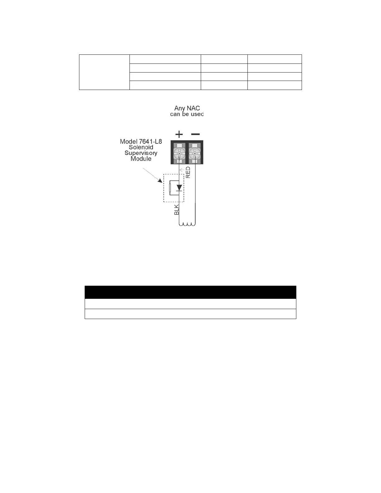
Figure 10-6 Wiring Configuration for Solenoid
*When ordering, order as P/N 7641-L8
10.7.1 Single Interlock Zone Releasing
A single interlock zone utilizes a minimum of two addressable detectors and a designated manual release switch.
Conditions Required for an Interlock Release Alert Output Activation
If any single addressable detector is activated, the “Interlock Release Alert” output will activate. This alerts the
user that the initial stages required for a release condition are present. (Also refer to Table 10-4).
Conditions required for a Detector Alarm and Interlock Release Alarm Output
Activation
If two or more addressable detectors, or a manual release switch activate, the “Detector Alarm” and “Interlock
Viking
11591 24 VDC 417
11595 24 VDC 417
11592NC 24 VDC 416
16360 24VDC 500
Important!
Only addressable detectors can be used. No conventional detectors can be used.
Each Single Interlock Zone input requires at least one manual release switch.
Table 10-3: Approved Releasing Solenoids
Releasing solenoid
Use 24 VDC, UL listed
1 solenoid per circuit
model in table 10-3

 Loading...


