Model IFP-2100/ECS Installation Manual LS10143-001SK-E
4-17
4. After the annunciator wiring to the panel has been completed (described in Section 4.6.2), replace the elec-
tronic assembly in the backbox. Place the bezel over the backbox and tighten the set screws on the bezel.
Figure 4-22 Flush Mounting the Backbox
4.6.1.2 Surface Mounting
The RA-1000 can be mounted directly to a surface or can be attached to a single, double, or four-square electrical
box. The Model 5860TG/TR trim ring kit is available for use when surface mounting.
1. Drill holes in the surface to match the screw holes on the backbox.
2. Fit the trim ring over the backbox.
3. Attach the backbox to the surface using screws provided.
4. After the annunciator wiring to the panel has been completed (described in Section 4.6.2), replace the elec-
tronic assembly in the backbox. Place the bezel over the backbox and tighten the set screws on the bezel.
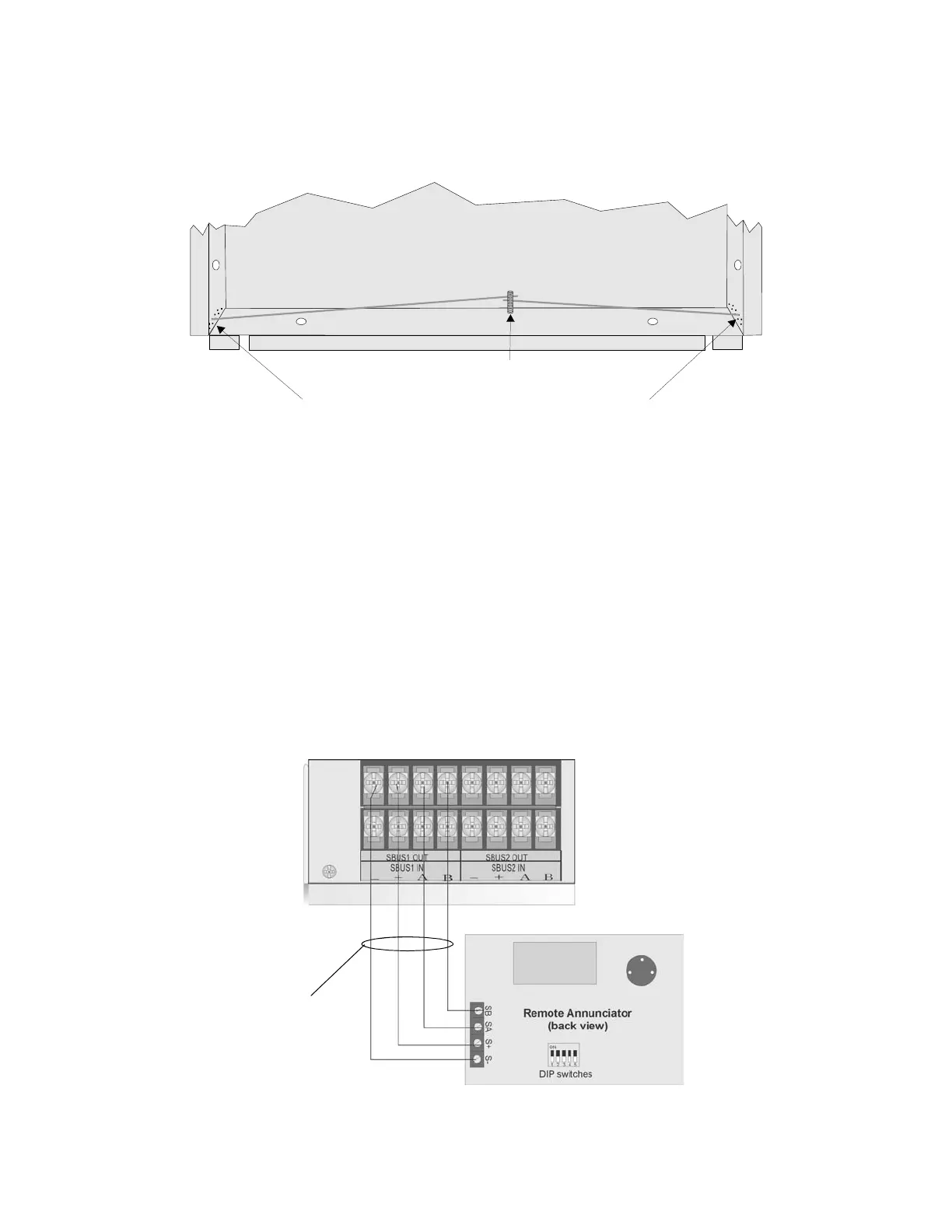
4.6.2 Model RA-1000 Connection to the Panel
Connect the RA-1000 to the panel as shown in Figure 4-23.
Figure 4-23 Model RA-1000 Connection to the Panel
Insert wires at an angle into the first holes past the sheet rock.
Secure the wires behind this screw.
Attach second set of wires to top of back box.

 Loading...


