Model IFP-2100/ECS Installation Manual LS10143-001SK-E
4-13
4. Place the trim ring over the backbox as shown in Figure 4-16.
Figure 4-16 Installing Trim Ring
5. Connect wires from the RA-2000 to the SBUS connectors on the FACP.
6. Attach the annunciator and door assembly to the backbox using screws provided (see Figure 4-14).
4.5.2 RA-2000 Connection to the Panel
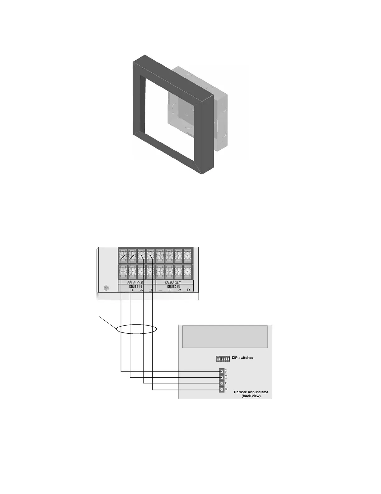
Connect the RA-2000 to the panel as shown in Figure 4-17.
Figure 4-17 Model RA-2000 Connection to the Panel
4.5.3 Temporary Programming Display
When an RFP-2100 is being initially setup, place an RA-2000 on the panel at address 63 or address 31 for an

 Loading...


