Model IFP-2100/ECS Installation Manual LS10143-001SK-E
3-11
1. The FACP can only support 5 devices w/LED’s on. The current draw has been added to the panels alarm current.
2. If using door holders, you do not need to consider door holder current for alarm/battery standby, because power is removed
during that time. However, during normal operation, door holders draw current and must be included in the 9.0A total current
that can be drawn from the panel.
3. Use next size battery with capacity greater than required.
4. Maximum SBUS address capacity is 63 SBUS modules. The practical limit is determined by the amount of SBUS bandwidth
consumed by each SBUS module. See section 4.13.2.
5. The
IDP-Beam-T draws a maximum of 500mA from auxiliary power when the test feature is used. This should be considered
when determining auxiliary power capacity but not calculated into current requirements for day to day operation.
6. The IDP-PhotoR is sold separately from the DNR. Current draw for the DNR + IDP-PhotoR is calculated by increasing the
“Number of Devices” column for each IDP-PhotoR used with a DNR.
7. The DNR housing does not include a Relay circuit board. If a relay is needed, be sure to add one to the IDP-Relay & IDP-Pho-
toR “Number of Devices” column for each DNR used for correct current calculations.
3.7.3 Current Draw Worksheet for SK SLC Devices
Use Table 3-3 to determine current requirements during alarm/battery standby operation when SK SLC devices
are installed. You can install up to 159 SK sensors per loop (2100 points max per panel) and 159 modules per
loop (2100 points max per panel).
Number of standby hours H
Multiply lines E and F. Total standby AH AH
Alarm sounding period in hours. (For example, 5 minutes = .0833 hours) H
Multiply lines E and H. Total alarm AH
AH
Add lines G and I.
3
AH
Multiply by the Derating Factor x 1.25
Total ampere hours
required
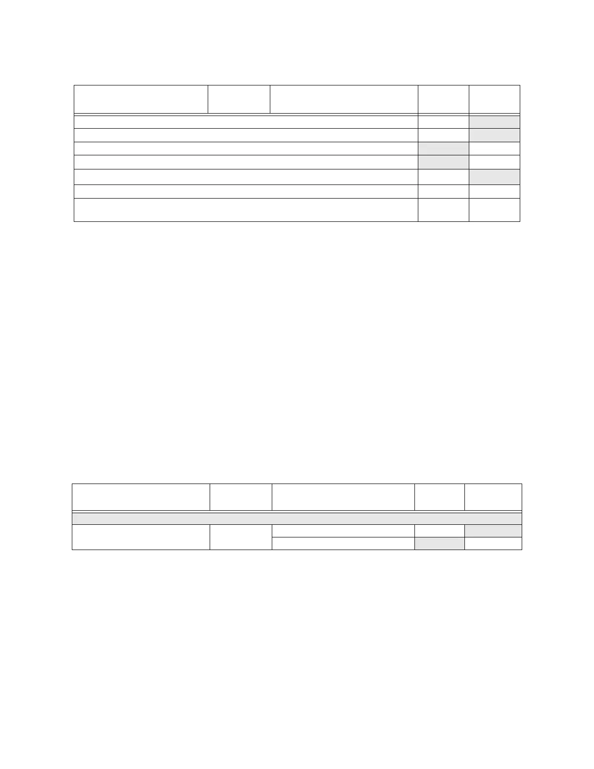
Table 3-3 Current Draw Worksheet for SK SLC Devices
Device # of Devices Current per Device
Standby
Current
Alarm
Current
For each device use this formula: This column X This column = Current per number of devices.
Fire Panel (Battery current draw) 1
Standby: 230 mA 230 mA
Alarm: 415 mA 415 mA
Table 3-2: Current Draw Worksheet for IDP SLC Devices
Device # of Devices Current per Device
Standby
Current
Alarm
Current
 Loading...


