Model IFP-2100/ECS Installation Manual LS10143-001SK-E
3-3
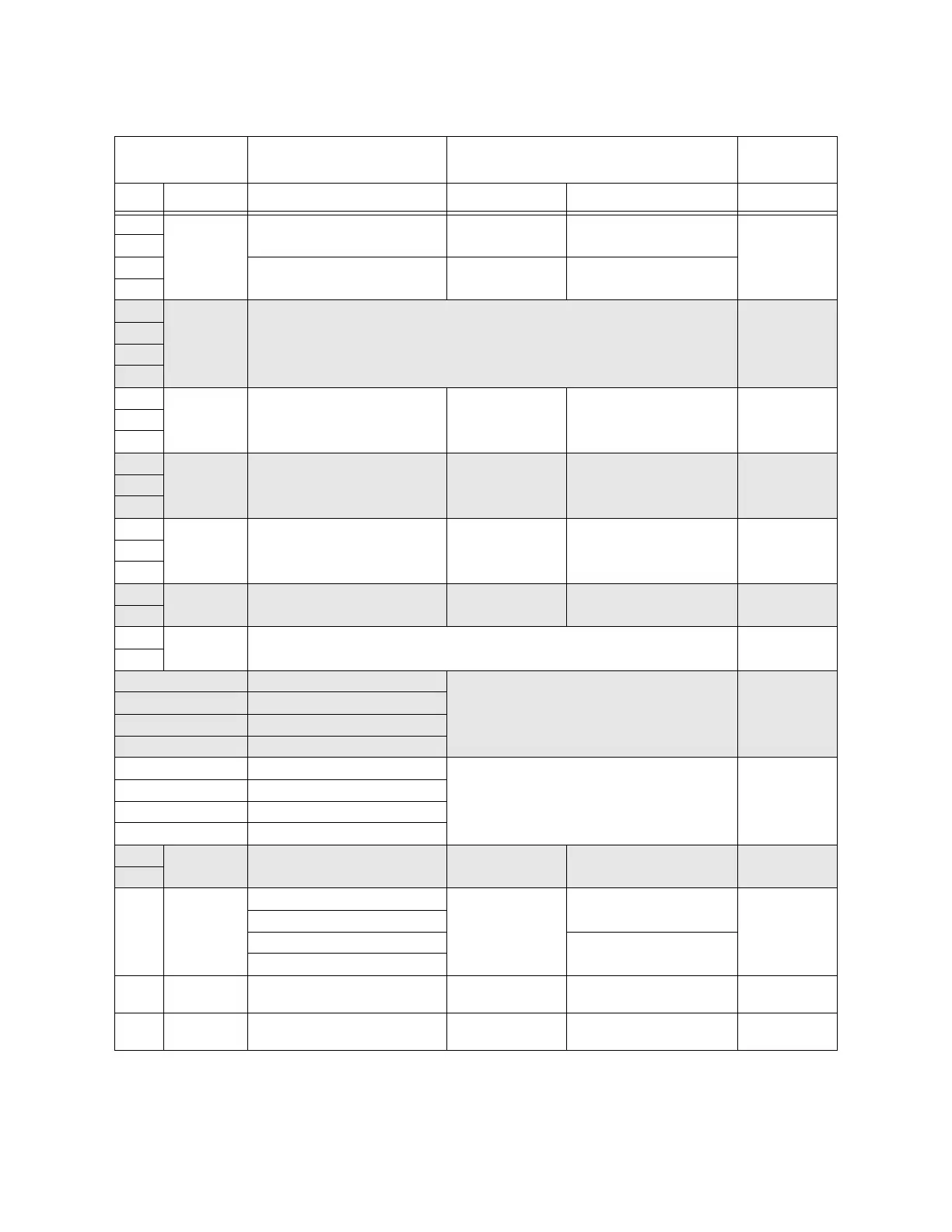
B
SBUS2 OUT
SBUS communication 5 VDC 100 mA 0Ω
A
+ SBUS power 24 VDC 1.0 A
-
B
SBUS2 IN
Used for Class A installations 0Ω
A
+
-
N.C.
RELAY 1
General Purpose Relay 1 24 VDC 2.5 A, resistive N/A
C
N.O.
N.C.
RELAY 2
General Purpose Relay 2 24 VDC 2.5 A, resistive N/A
C
N.O.
N.C.
TROUBLE
Trouble Relay 24 VDC 2.5 A, resistive N/A
C
N.O.
S-
SLC OUT
SLC terminals 32 VDC 150 mA 0Ω
S+
SC-
SLC IN
Used for Class A installations 0Ω
SC+
Ring Phone Line 1 Telco Ring N/A 0Ω
Tip Phone Line 1 Telco Tip
Ring Phone Line 1 Premises Ring
Tip Phone Line 1 Premises Tip
Ring Phone Line 2 Telco Ring N/A 0Ω
Tip Phone Line 2 Telco Tip
Ring Phone Line 2 Premises Ring
Tip Phone Line 2 Premises Tip
+
Battery
Battery Connection 24 VDC 1.12 A N/A
–
P3
EXT. Comm
Cellular
Connection
B
input 0Ω
A
S+
55 mA, 95 mA
S-
P7
Data
Network
Used for SK-NIC 24 VDC 21 mA
0Ω
P8
Voice
Network
Used For ECS-NVCM 24 VDC 59 mA
0Ω
Table 3-1 Terminal Descriptions and Electrical Specifications
Terminal Label Description Rating
Earth Ground
Faults
Voltage Current
 Loading...


