Serial essernet
®
interface (SEI1)
FB 798819 / 05.18 53
F1
Fuse T 1 A / 250 V
Never repair or bridge the device fuses that are installed or
replace them with anything other than the stated type.
S2 - Mode DIP switch – for setting the programming mode of the SEI1 Type
System 8000 / IQ8Control-Remote FACP (Part No. 784859)
Normal operating mode for all other versions (factory setting)
S3 - Reset RESET button, changed parameters will be activated.
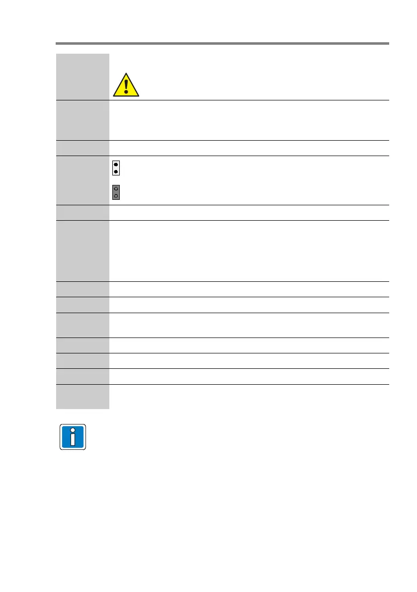
J1
Programme
open: EEPROM write protection active
(factory setting)
closed: EEPROM write protection de-activated
(required only for programming)
J3,J4,J5,J6 Jumper EMC protection for essernet
®
SI 01 / SI 02 LED Interface function display
LED red : failure
LED yellow : data / communication
SI 01 RS485 interface, internal
SI 02 Interface module RS232/V.24 or TTY/CL 20 mA
V 11,12,13 LED indicators (red, yellow, green), see Chapter 10.1
X2 Connector operating voltage
X5 Alternative slot for essernet
®
module (Part No. 784840.10 / 784841.10) during
installation in the FACP or extension housing
X7 Connector essernet
®
X12 Connection service PC. Only required with SEI1 (Part No. 784859)
X13 Protective earth (PE) connector
X14 Slot for essernet
®
module (Part No. 784840.10 / 784841.10) during installation
in the housing (Part No. 788606)
• Use clearly identified cable I-
Y (St) Y n x 2 x 0,8 mm or comparable and
employ only shielded twisted pair cables with special designation for fire
detection, and consider furthermore the requirements of the local standard!
• The shielding must be connected for EMI protection of the cable!
• All voltage and signal lines must be secured to prevent slipping by using a
suitable attachment materials such as plastic cable binders.
• Take care to ensure that no cables are pinched or damaged.