Serial essernet
®
interface (SEI1)
FB 798819 / 05.18 55
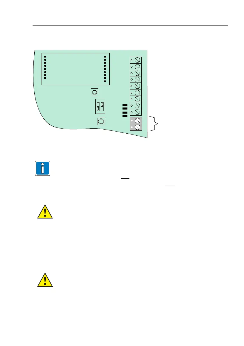
10.2.2 Connecting the RS485 interface
Each SEI1 provides an integrated RS-485 interface as a factory standard.
Interface
module
RS485
RxD + (A)
RxD - (B)
SIO 1
J 9
J 8
Fig. 9: Terminal SIO 1
The RS485 interface condition is displayed with both LED (SI 01 red/yellow)
• If the RS485 interface is used for
data transmission between the main
network and the sub net, e.g. in remote operation, the symmetry resistors
may be activated at only one serial essernet
®
interface.
• For activation of the symmetry resistors, close both solder bridges J8 + J9
(see Fig.9).
• Max. line length 1000 m between the interface and the external equipment.
Observe permitted torque (max. 0.4 Nm) of the terminals!
10.3 essernet
micro module
In the serial essernet
interface, an essernet
module can be used for networking up to 31
devices, such as ESSER fire alarm control panels and management systems.
• Only essernet
modules using the same transmission rate may be combined
in one network!
• Implement the essernet
surge protection or expanded EMC protection using
special LAN protection devices.