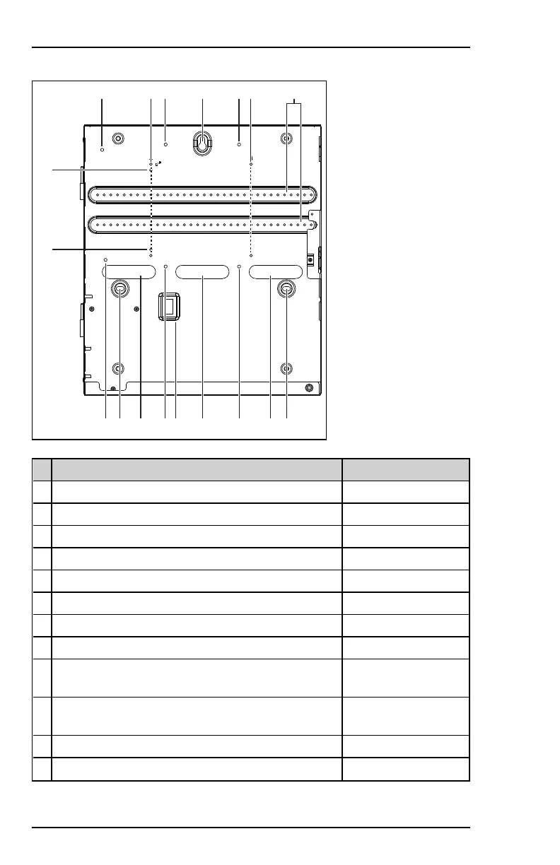
Back:
H I IH J H K
JJ LLL M HHH
N
N
# Purpose Dimensions
A Wiring knockout, extra large (x6) Diameter 13/8in
B Knockout for optional 4G/LTE module's antenna (x2) Diameter 11/16in
C Knockout with folded edge (x3) Diameter 11/8in – 7/8in
D Hinge (x2)
E Wiring knockout, small (x1) Diameter 7/8in
F Wiring knockout, large (x3) Diameter 11/8in
G AC power inlet (x1) 11/16in x 13/16in
H Attachment point for cable tie (x6)
I Screw hole for mounting MPI Control Panel (x2above and
x2below mounting rails)
Diameter 3/16in
J Screw hole for mounting cabinet on wall (x3) See detail illustration
further below.
K Mounting rails for MPI modules (x2)
L Wiring knockout (x3) 31/8in x 13/16in
28 800-23044 Rev. A draft_11
Installation and Setup Guide Honeywell MAXPRO Intrusion MPIP2000U/3000U Series
 Loading...