Honeywell MAXPRO Intrusion MPIP2000U/3000U Series Installation and Setup Guide
800-23044 Rev. A draft_11 37
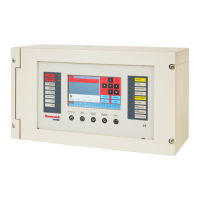
# LED Colour Description
B Green Power input available on main board.
Off No power available on main board.
C Green V-Plex1: loop OK.
Off V-Plex1: loop shorted or data bus not running.
D Green AUX1/IB2 bus1: power on AUX1 is available.
Off PTC for AUX1 is resetting, or other trouble on the bus.
E Amber (left) Ethernet amber LED (left): network connection is
working.
Green (right) Ethernet green LED (right): flashes when the system
is sending or receiving data over the network.
F Green AUX3: power on AUX3is available.
Off PTC for AUX3 is resetting.
G Green AUX2/IB2 bus2: power on AUX2 is available.
Off PTC for AUX2 is resetting, or other trouble on the bus.
This LEDis only available on the MPIP3000 series.
H Green V-Plex2: loop OK.
Off V-Plex2: loop shorted or data bus not running.
This LEDis only available on the MPIP3000 series.
3.6 Connecting the Cabinet Tamper Switches
The cabinet comes with a tamper switch in the cabinet door to prevent opening
of the cabinet door. Use the included cable to connect the tamper switch to the
control panel (D on page34).
Optionally, there is a knockout available in the cabinet back that can be used to
fit an additional tamper switch to prevent removalof the cabinet from the wall.
From To Control Panel Terminal
Tamper switch in cabinet door T-LID
Tamper switch in cabinet back
(optional, not included)
T-WALL
The system will report tamper events on Area1, the system area.
l If Area1 is disarmed, the system will report the tamper event as a fault
condition.
l If Area1 is armed, the system will report the tamper event as an alarm.
 Loading...