Honeywell MAXPRO Intrusion MPIP2000U/3000U Series Installation and Setup Guide
800-23044 Rev. A draft_11 47
For non-polarized devices:
…
…
2K
EOLR
Bell Bell
Horn
+
–
A B B C D E
FF
A BELL terminals on ControlPanel D To other devices
B Polarizing diodes (must mount at
indicating device)
E Terminating end-of-line resistor
C Polarizedfire indicating device
(e.g. horn)
F Non-polarized burglary indicating
devices (e.g. bells)
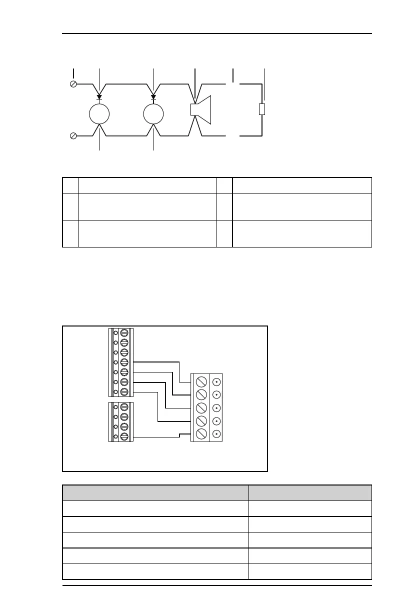
3.9.3 Installing a Self-Activating Bell (SAB)
The Triggers terminals (P on page34) allow for connecting an external siren
with tamper protection. The illustration below shows a typical 5-wire
connection.
2
3
4
+12V
1
TAMP
+12V
NC
C
NO
–
– HOLD OFF
+ HOLD OFF
TR
SIREN
STROBE
SABCONTROL P
ANEL
MPIPxxxx
RELAY 1 TRIGGERS
From control panel terminal To SAB terminal
Trigger2 Strobe
Trigger1 Siren / Bell
TAMP (AUX) Tamper return / TR
+12V (AUX3) Hold off + / +Ve
– (on Relay1 terminal block) Hold off – / –Ve
 Loading...