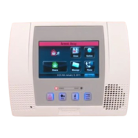
Honeywell MAXPRO Intrusion MPIP2000U/3000U Series Installation and Setup Guide
800-23044 Rev. A draft_11 35
# Item
Terminal
or
connector
Connect with
H Vplex BUS1 + V-Plex bus1+
– V-Plex bus1–
I IB2 BUS 1 +12V AUX1 12VDC supply terminalfor devices
connected to IB2 bus1.
– 0VDC supply terminal for devices connected
to IB2 bus1.
C IB2 busC
D IB2 busD
J IB2 bus1 Quick connect plug for IB2 BUS1 (can be used for
module stacked on top of main board; quick connect
cable is included).
K LTE Cell
Radio
USB and
PWR/IO
Connectors for the 4G/LTE module
L For future use.
M Ethernet WAN Network with internet connection to the
cloud.
N Relay2 NC Normal Closed terminal, output relay2
C Common terminal, output relay2
NO Normal Open terminal, output relay2
Relay2 is only available on the MPIP3000 series.
O Relay1 NC Normal Closed terminal, output relay1
C Common terminal, output relay1
NO Normal Open terminal, output relay1
– Spare 0VDC connector.
P Triggers For outputs. For details, see Wiring Outputs on page48.
Can also be used for a self-activating bell. For details, see
Installing a Self-Activating Bell (SAB) on page47.
Q Jumpers for low-voltage triggers. For details, see Wiring Outputs on
page48.
R Zones9, 10 For zones (sensor contact inputs). Can be used for 2-wire
smoke sensors or as standard burglary zones.
For details, see Wiring Inputs (Zones) on page39.
 Loading...
