Note
Any unused hardwire zones should always have a 2K resistor wired
across the zone terminals to terminate them.
Possible wiring types are:
l Supervised EOLR (normal open or normal closed)
l Double balanced
l Triple balanced.
All types are described in detail further below.
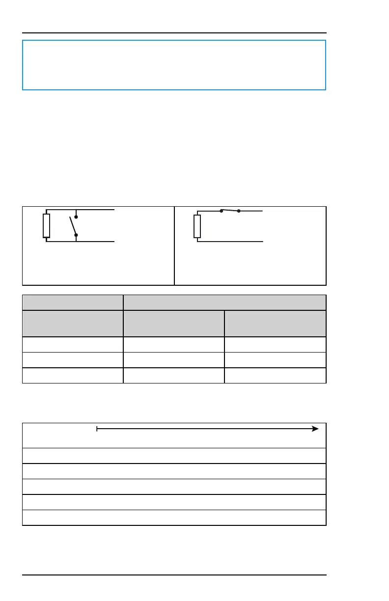
3.8.2.1 Supervised EOLR
For a normally open circuit, you wire
the sensor (N.O.) in parallel to the
EOL resistor R1.
For a normally closed circuit, you wire
the sensor (N.C.) in series with the
EOL resistor R1.
Message to the system
State at input
terminals
Standard US Burglary Standard US Fire
Short circuit Alarm Alarm
R1 ohms Ready Ready
Open circuit Alarm Fire & CO trouble
Acceptable EOL values for R1 are defined in the table below. The electrical
bands for each R1 value are indicated below:
Alarm < Ready < Alarm / Fire & CO trouble
R1 = 1K
500Ω 1,500Ω
R1 = 2K/2K2
1,000Ω 3,000Ω
R1 = 3K3
2,000Ω 4,000Ω
R1 = 5K6
2,800Ω 8,400Ω
40 800-23044 Rev. A draft_11
Installation and Setup Guide Honeywell MAXPRO Intrusion MPIP2000U/3000U Series
 Loading...