For example, for R1= R2 = 1K, the system will go in:
l Tamper state if the resistance falls below 800ohms.
l Ready state if the resistance is between 800 and 1,500ohms.
l Alarm state if the resistance is between 1,500 and12,000ohms.
l Tamper state if the resistance is above 12,000ohms.
Note
l Resistor tolerance 1% or better.
l Capable of up to 100ohms resistance.
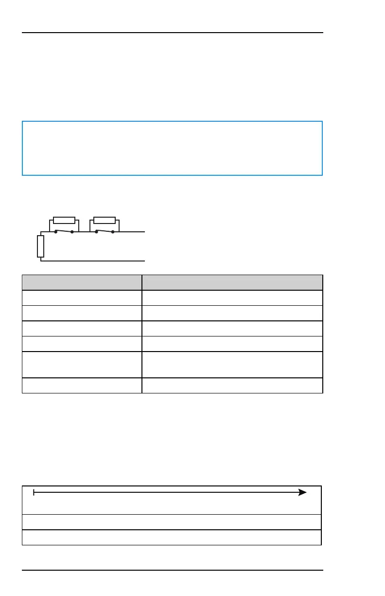
3.8.2.3 Triple Balanced
R1
R2 R3
ALARM
N.
C.
TROUBLE
N.C.
State at input terminals Message to the system
Short circuit Tamper
R1 ohms Ready
R1 + R2 ohms Alarm
R1 + R3 ohms Trouble
R1 + R2 + R3ohms Mask condition (trouble when system is
disarmed; alarm when system is armed)
Open circuit Tamper
Acceptable values for for R1, R2, and R3are:
l R1 = 1K
l R2 = 1K
l R3 = 3K.
The electrical bands are indicated below:
Tamper < Ready < Alarm < Trouble < Mask < Tamper
800Ω 1,800Ω 2,500Ω 4,500Ω 10,000Ω
42 800-23044 Rev. A draft_11
Installation and Setup Guide Honeywell MAXPRO Intrusion MPIP2000U/3000U Series
 Loading...