100 MPA2C3 Installation Guide
RS485 Bus Termination.
An RS485 bus must be terminated with a resistor at both ends of the RS-485 bus.
If the MPA2C3 panel is at the beginning or end of the I/O Devices RS485 bus, then
the bus must be closed with 120 Ohm resistor. On Dipswitch SW3 both bit 5 and 6
(EOL I/O DEV) must be set to ON position to add the resistor to the RJ45 I/O
DEVICES RS485 communication wires.
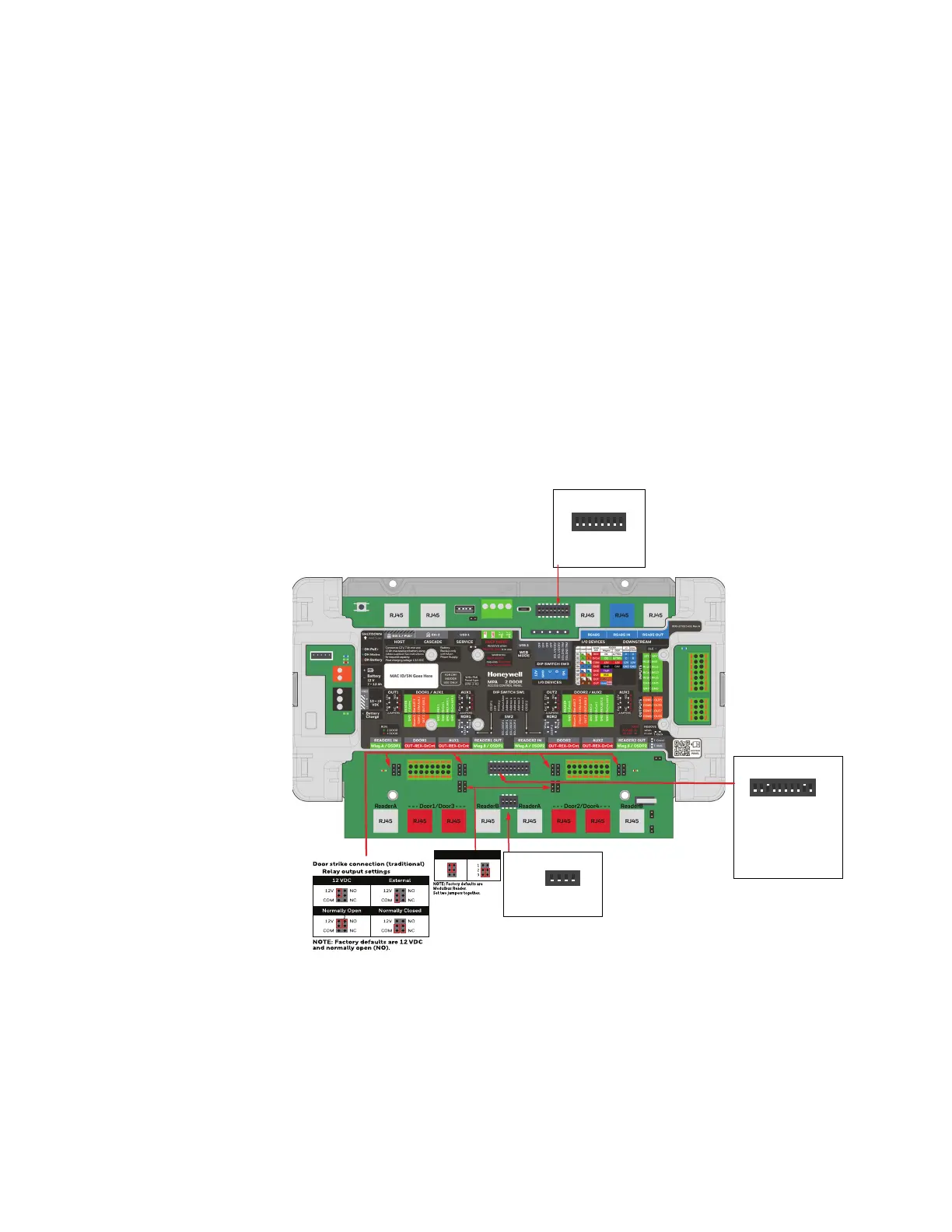
Setting DIP Switches and Jumpers
The access control panel involves 3 DIP Switches and 14 jumpers. The switches are
used to configure the IP addresses, to configure the panel for different reader con-
nections, to configure primary panel and so forth. The jumpers are used for Door
output power source selection and relay contact type (2 per door), for reader wie-
gand/OSDP selectio"Wiegand Reader Wiring" on page 3-52 for FACP bypass
(see".FACP Jumper" on page 3-106) and for Back tamper bypass ("T-Back
Jumper" on page 3-106).
DIP Switch 3 (SW3)
OFF
12345678
ON
Set
1-4 OFF
5 EoL RS485 bus I/O Devices
6 EoL RS485 bus I/O Devices
7 EoL RS485 bus Downstream Panels
8 EoL RS485 bus Downstream Panels
Set
DIP Switch 1 (SW1)
OFF
12345678910
ON
1Wiegand READER 1(A/B)-OSDP1
2 OFF
3 secondary /Primary panel(ON)
4 User IP address /Deafault IP address
5 Address 5
6 Address 4
7 Address 3
8 Address 2
9 Address 1(ON)
10 Wiegand READER 2(A/B)-OSDP2
Set
DIP Switch 2 (SW2)
OFF
1234
ON
1 EoL OSDP1
2 EoL OSDP1
3 EoL OSDP2
4 EoL OSDP2
Wiegand Reader
OSDP Reader
 Loading...


