PAGINA - 8 Installation and programming manual AM-1224
NOTIFIER ITALIA Doc. M-124.1-AM1224-ENG Rev A.1 AM-1224_manu
CN0 terminals
CN1 terminals
Terminal #
CN0
Description
Note
1
ALARM Relay NO-NC
2
ALARM Relay Common
Max 2A resistive 30Vdc,
Contact NO-NC selectable via
JALL Jumper
3
FAULT Relay NO-NC
4
FAULT Relay Common
Max 2A resistive 30Vdc
Contact NO-NC selectable via
JGST Jumper
5
SOUNDER (–)
(shown polarity, normal condition)
6
SOUNDER (+)
(shown polarity, normal condition)
Protected with 1A Fuse
Total current: 1A (Sounder+User )
End of Line resistor: 47K 5%
7
TX
8
RX
9
GND
RS232 serial interface input
(used for UPLOAD)
10
11
+ 24Vdc 1A User
12
13
GND User
Protected with 1A Fuse
Total current: 1A ( Sounder+User )
14
Auxiliary input (External power supply Fault indication)
15
Auxiliary input (level 2 access )
16
Auxiliary input (Evacuation)
17
Auxiliary input (Technical Alarm)
End of Line resistor 2k7 ohm 5% 1/4W
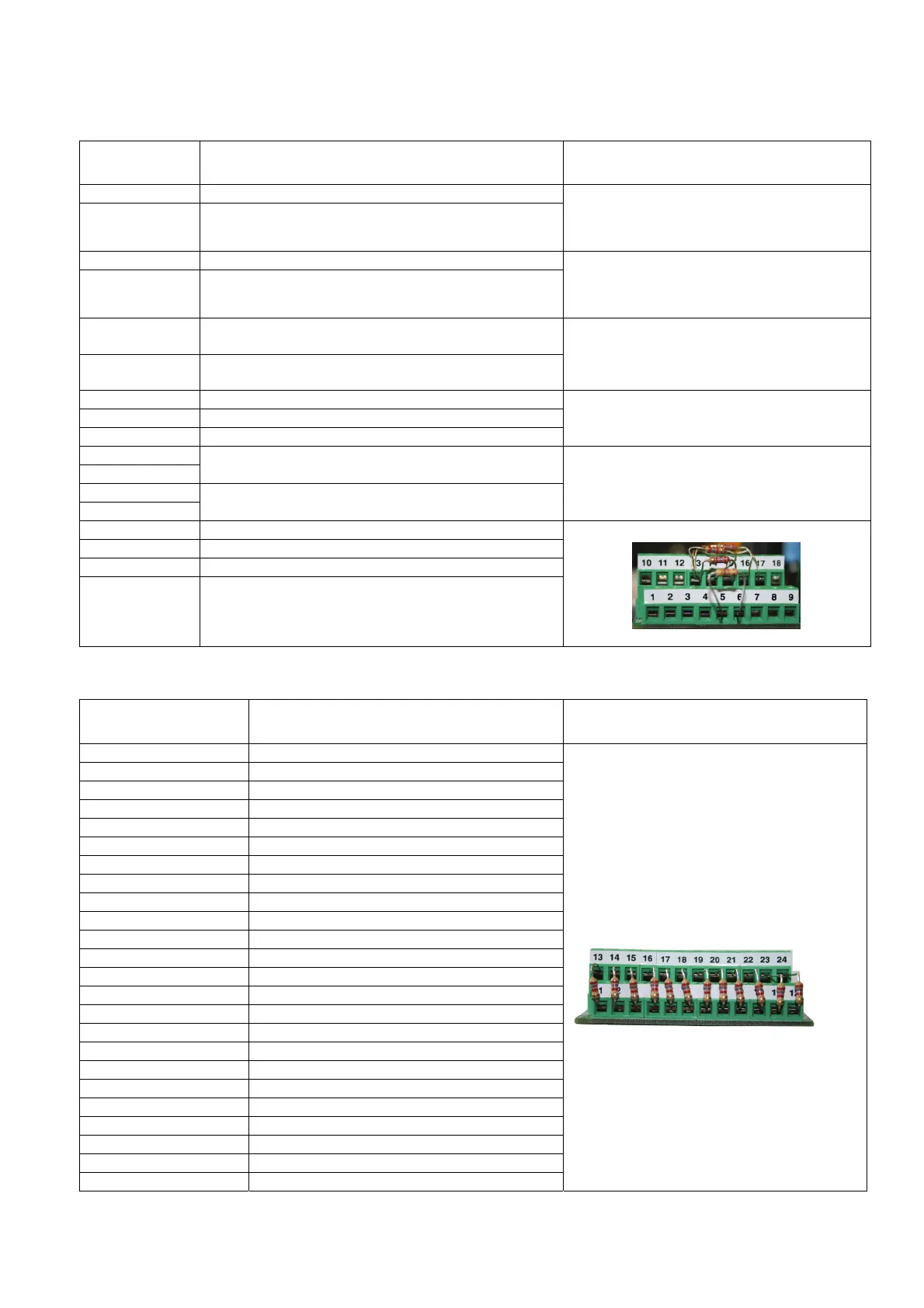
Terminal # CN1
Description Note
1 Line 1 - (GND)
2 Line 2 - (GND)
3 Line 3 - (GND)
4 Line 4 - (GND)
5 Line 5 - (GND)
6 Line 6 - (GND)
7 Line 7 - (GND)
8 Line 8 - (GND)
9 Line 9 - (GND)
10 Line 10 - (GND)
11 Line 11 - (GND)
12 Line 12 - (GND)
13 Line 1 +
14 Line 2 +
15 Line 3 +
16 Line 4 +
17 Line 5 +
18 Line 6 +
19 Line 7 +
20 Line 8 +
21 Line 9 +
22 Line 10 +
23 Line 11 +
24 Line 12 +
End of Line resistor
2k7 ohm 5% 1/4W

 Loading...


