Notifier SLC Wiring Manual — P/N 51253:U9 12/3/2021 21
Two-Wire SLC - Class B Wiring Requirements
2.2 Two-Wire SLC - Class B
2.2.1 Measuring Loop Resistance
T-tapping of the SLC wiring is permitted for two-wire Class B configurations. The total DC resistance from the control panel to each
branch end cannot exceed:
• NOTE: 35 ohms for SLM-318 (CLP-2PCB) with self-test detectors installed.50 ohms for SLM-318/N16, NFS-320, NFS2-640,
NFS-640, LCM-320, LEM-320, LIB-200A, and LIB-400.
NOTE: 35 ohms for current SLM-318 (CLP-2PCB) with self-test detectors installed; 23 ohms for initial release SLM-318 (CLP-
PCB) with self-test detectors installed.
• 40 ohms for AFP-100, AFP-200, AFP-300/400, LIB-200, and AIM-200.
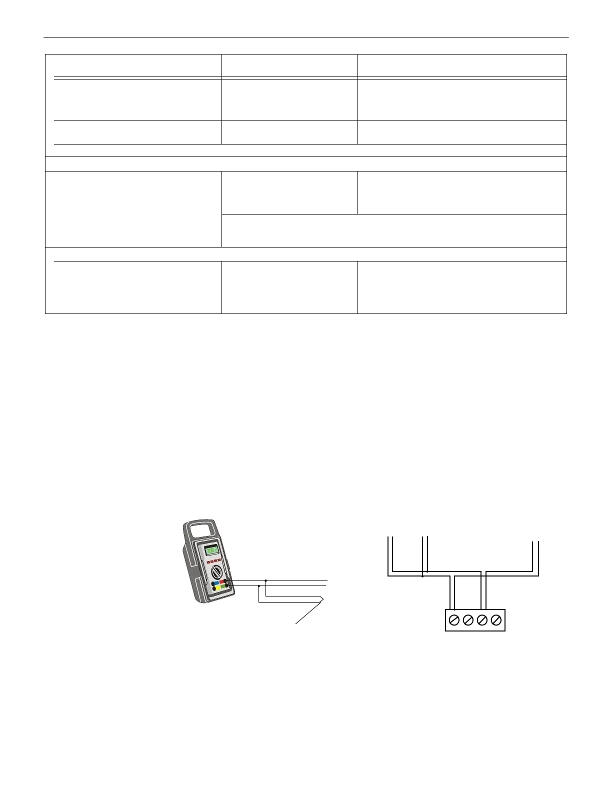
Measure DC resistance as detailed and shown below:
1. With power removed, short the termination point of one branch at a time and measure the DC resistance from the beginning of the
SLC to the end of that particular branch.
2. Repeat this procedure for all remaining branches in the SLC.
In Figure 2.1, Branches A, B, and C all begin at the SLC terminal, even though Branch B is T-tapped.
2.2.2 Measuring Total Wire Length
The total wire length of all combined branches of one SLC cannot exceed the limits set forth in each system’s instruction manual. Deter-
mine the total length in each SLC by summing all wire segments. In Figure 2.1 above, the picture on the right shows an SLC with 3
branches. Figure 2.2 below shows the same SLC divided into segments. The total length of the SLC is determined by adding the lengths
of Segment 1 + Segment 2 + Segment 3 + Segment 4 + Segment 5. No segment should be summed twice.
Twisted-shielded pair, 12 to 18 AWG. 40
ohms, maximum per length of Class A and X
loops. 40 ohms per branch maximum for
Class B loops.
10,000 ft. (3,048 m)
8,000 ft. (2,438.4 m)
4,875 ft. (1,485.9 m)
3,225 ft. (982.98 m)
12 AWG (3.31 mm²)
14 AWG (2.08 mm²)
16 AWG (1.31 mm²)
18 AWG (0.82 mm²)
Untwisted, unshielded wire, in conduit or
outside of conduit.
1,000 ft. (304.8 m) 12 to 18 AWG (3.31 mm² to 0.82 mm²)
Note: Twisted-unshielded pair wire is not recommended for use with this panel.
LIB-200 on AM2020/AFP1010 (See Table 2.1 for LIB-200A or LIB-400.)
Twisted-shielded pair. Maximum loop
resistance is 40 ohms. Maximum length is
10,000 ft. per channel (NFPA Class B) or
10,000 ft. total twisted pair length (NFPA
Class A and X loops). Maximum loop current
is 200 mA (short circuit) or 100 mA (normal).
10,000 ft. (3,048 m)
8,000 ft. (2,438.4 m)
4,875 ft. (1,485.9 m)
3,225 ft. (982.98 m)
12 AWG (3.31 mm²)
14 AWG (2.08 mm²)
16 AWG (1.31 mm²)
18 AWG (0.82 mm²)
If the wiring connected to the LIB-200 leaves the building it must be in conduit. It can not exceed
1000 m (1093 yards), must not cross any power lines, and must not be in the vicinity of any high
voltage. These outdoor wiring restrictions do not apply to the LIB-200A or the LIB-400.
System 5000 with AIM-200
Twisted-shielded pair. Maximum loop
resistance: 40 ohms.
Maximum loop voltage: 27.6 VDC. Maximum
loop current: 200 mA (short circuit) or 100 mA
(normal operation).
10,000 ft. (3,048 m)
8,000 ft. (2,438.4 m)
4,875 ft. (1,485.9 m)
3,225 ft. (982.98 m)
12 AWG (3.31 mm²)
14 AWG (2.08 mm²)
16 AWG (1.31 mm²)
18 AWG (0.82 mm²)
FACP:
Wire Type and Limitations
Recommended
Max. Distance
Wire Gauge
Table 2.2 Wiring: AFP-100, AFP-200, AFP-300/400, LIB-200, AIM-200 (2 of 2)
SLC-meas5.wmf
SLC Out
Branch
Short Point
SLC Terminal
Block
B+ B–
Branch A Branch B Branch C
Figure 2.1 Measuring DC Resistance of a Two-Wire SLC

 Loading...


