Notifier SLC Wiring Manual — P/N 51253:U9 12/3/2021 75
Appendix D: Intelligent Detector Base Layouts for Legacy Devices
For Class A power-supervision requirements, refer to Appendix A.2, “Supervising 24 VDC Power”, on page 66.
D.1 Wiring a Detector Base
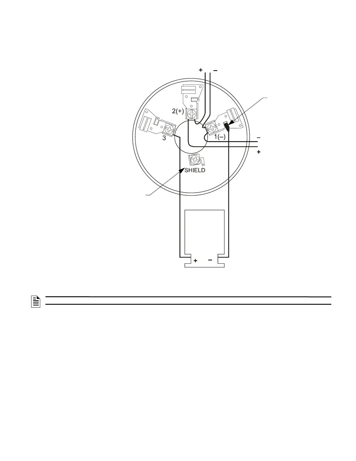
Figure D.1 shows typical wiring of the B710LP or B501 detector base connected to an SLC. An optional RA100Z Remote LED Annun-
ciator is shown connected to the base.
To next device
on SLC
SLC
S
L
C
-
B
5
0
1
w
i
r
e
.
w
m
f
RA100Z
Remote LED
Annunciator
(Optional)
B501 only: For connection of
cable shield
Use a female disconnect
to wire the RA100Z (–) to
Terminal 1 (–).
Figure D.1 Wiring of the B710LP or B501 Detector Base
NOTE: The B710LP base wiring is identical to the B501, except there is no shield terminal.

 Loading...


