Notifier SLC Wiring Manual — P/N 51253:U9 12/3/2021 23
Control Panel Terminal Blocks Wiring Requirements
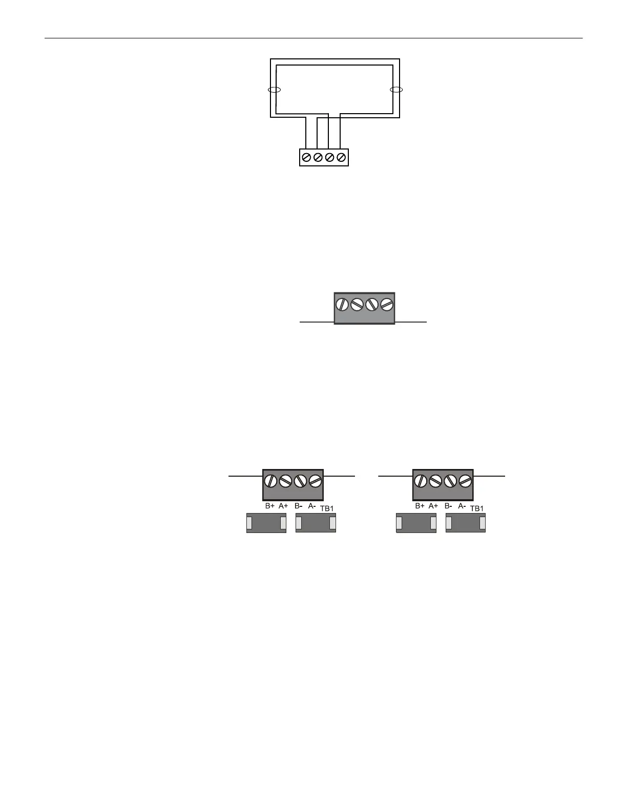
2.4 Control Panel Terminal Blocks
2.4.1 N16 with SLM-318 Signaling Loop Module
N16 supports from one to ten SLC loops. Connect from one to three PMB-AUX Power Module Boards to the panel, and connect from
one to five SLM-318 Signaling Loop Modules to each PMB-AUX. Loops can be either CLIP mode or FlashScan mode. SLC Loops con-
nect to TB1 on the SLM-318.
Connections are the same on current SLM-318 (silkscreened “CLP-2PCB”) and initial release (silkscreened “CLP-PCB”).
2.4.2 NFS2-3030 and NFS-3030 with LCM-320, LEM-320
The NFS-3030/NFS2-3030 supports up to five pairs of loop control and expander modules, providing from one to ten SLC loops. Loops
can be either CLIP mode or FlashScan mode. SLC loops connect to TB1 on the LCM-320 or LEM-320.
B–A+B+ A–
SLC channel B
(output loop)
SLC channel A
(return loop)
SLC Terminal Block
Figure 2.4 Measuring the Wire Length of a Four-Wire SLC
SLC Loop Connections
on SLM-318 Modules
SLM318-SLC-TB.wmf
Figure 2.5 N16 with SLM-318: SLC Loop Connections and Wiring
SLC Loop Connections
on Loop Expander Module
SLC Loop Connections
on Loop Control Modules
LEM320-SLC-TB.wmf
Figure 2.6 NFS2-3030, NFS-3030 SLC Loop Connections and Wiring

 Loading...


