36 Notifier SLC Wiring Manual — P/N 51253:U9 12/3/2021
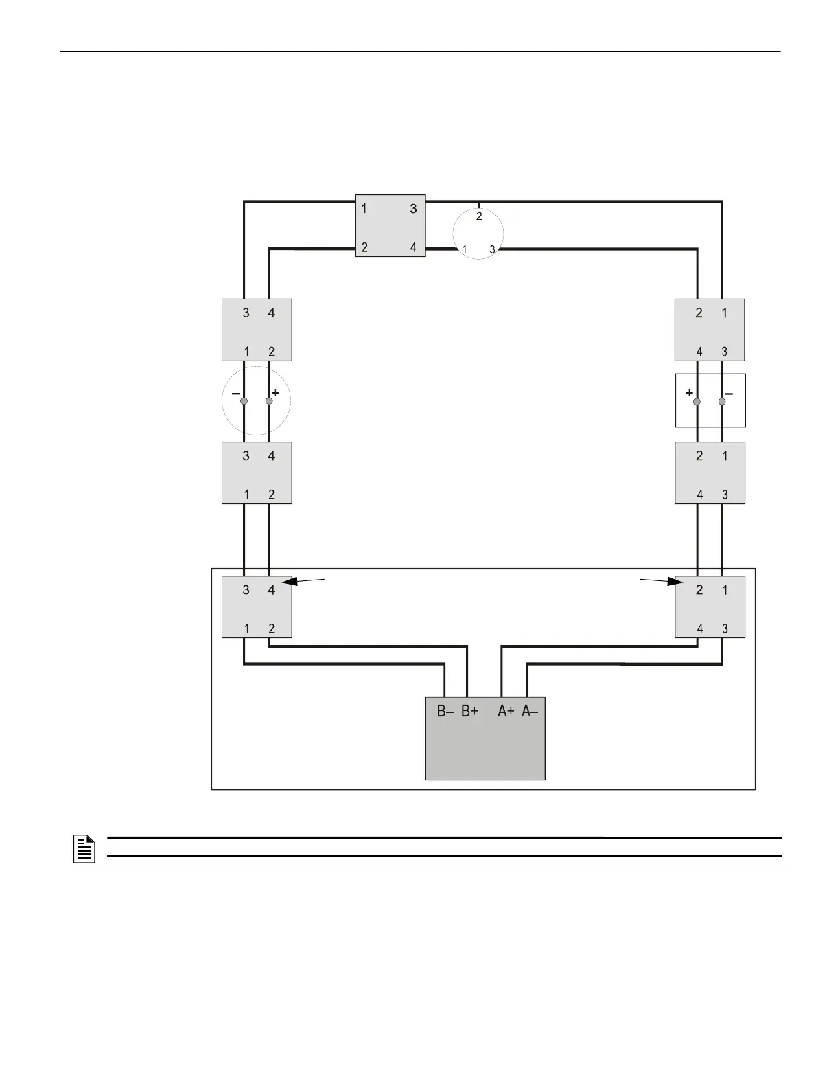
SLC Circuits with Isolators NFPA Class X SLC Using an Isolating Device
5.6 NFPA Class X SLC Using an Isolating Device
Class X operation requires using a combination of isolator detector bases and isolator modules or isolator modules before and after a
non-isolator device. Flanking each device with an isolator provides fault protection to all other devices on the loop.
• T-tapping is NOT allowed within the Class X wiring configuration.
• When a non-isolator base or pull station is used, install isolator modules on both sides of devices.
• When an isolator base is used in conjunction with an isolator module, install the isolator module as shown in Figure 10.3.
• There must be a close-nipple connection between a device and the isolator bases or modules that protect it.
SLC-style7iso.wmf
SLC Out
SLC Return
Addressable
Detector
Two-wire Isolator
Detector
Addressable
Pull Station
Control Panel
AFP-100, AFP-200, AM2020/AFP1010,
System 5000 with AIM-200:The first
isolator module on SLC Out and SLC
Return must be contained within the
same enclosure as the FACP, or these
isolator modules must be connected
within 20 ft. (6.1 m) of the FACP
enclosure in conduit.
Isolator
Module
Isolator
Module
Isolator
Module
Isolator
Module
Isolator
Module
Isolator
Module
Isolator
Module
The first isolator module on SLC Out and SLC Return is optional
for N16, NFS-320, NFS2-640, NFS2-3030, NFS-640, NFS-3030,
AFP-300, and AFP-400 because the panels provide the
functionality.
Figure 5.7 NFPA Class X SLC Using Isolator Modules
NOTE: See Figure 10.3, “Wiring a B224BI-WH/B224BI-IV Isolator Base Mounting Plate” on page 56.

 Loading...


