40 Notifier SLC Wiring Manual — P/N 51253:U9 12/3/2021
Monitor Modules NFPA Class A IDC Using Monitor Modules
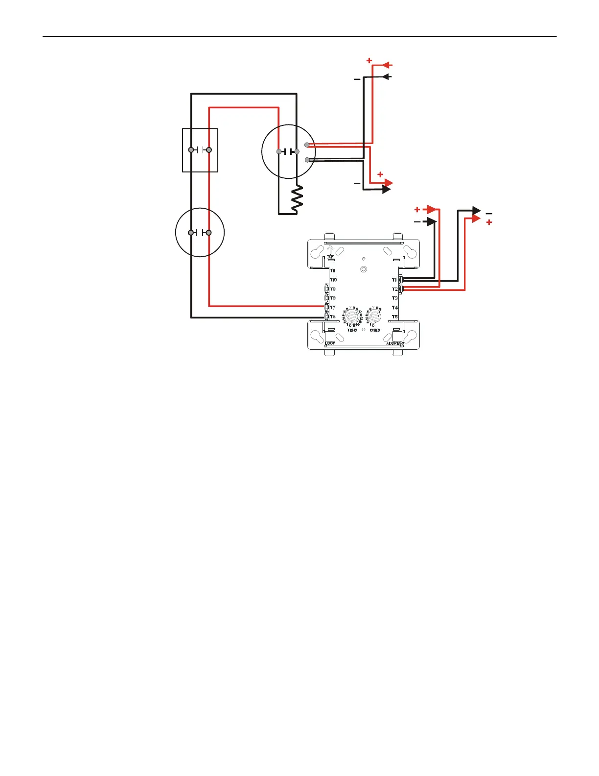
6.4 NFPA Class A IDC Using Monitor Modules
Connect the SLC wiring to the module terminals 1 (–) and 2 (+).
Each FMM-1 module takes one address on the SLC. Use the rotary switches on the module to set it to the required SLC address.
Figure 6.7 shows typical wiring for a supervised and power-limited NFPA Class A IDC using the FMM-1 module.
Module installation notes:
1. The Initiating Device Circuit (IDC) is supervised and current-limited to 210 microamps @ 24 VDC (nominal).
See Appendix A, “Power Considerations”, on page 66 for information on monitoring 24 VDC power.
2. The IDC provides the following services (do not mix):
• Fire alarm service
• Automatic and manual waterflow alarm service with normally open contact devices
• Sprinkler supervisory service with normally open contact devices
• Security service
3. Refer to the Device Compatibility Document for compatible smoke detectors.
47K ELR
(supplied
with module)
Heat
detector
SLC
FMM-1
IDC
24 VDC Power
Filtered, Regulated,
Resettable
24 VDC
Four-wire
Detector Base
Manual pull
station
From Supply
To Next IDC
or
Supervision Device
SLC-idcB1tpH.wmf
Figure 6.6 Typical Class B IDC Wiring with FMM-1

 Loading...


