Notifier SLC Wiring Manual — P/N 51253:U9 12/3/2021 57
Wiring a Sounder Base Intelligent Detectors, Intelligent Detector Bases, and Wireless Gateway
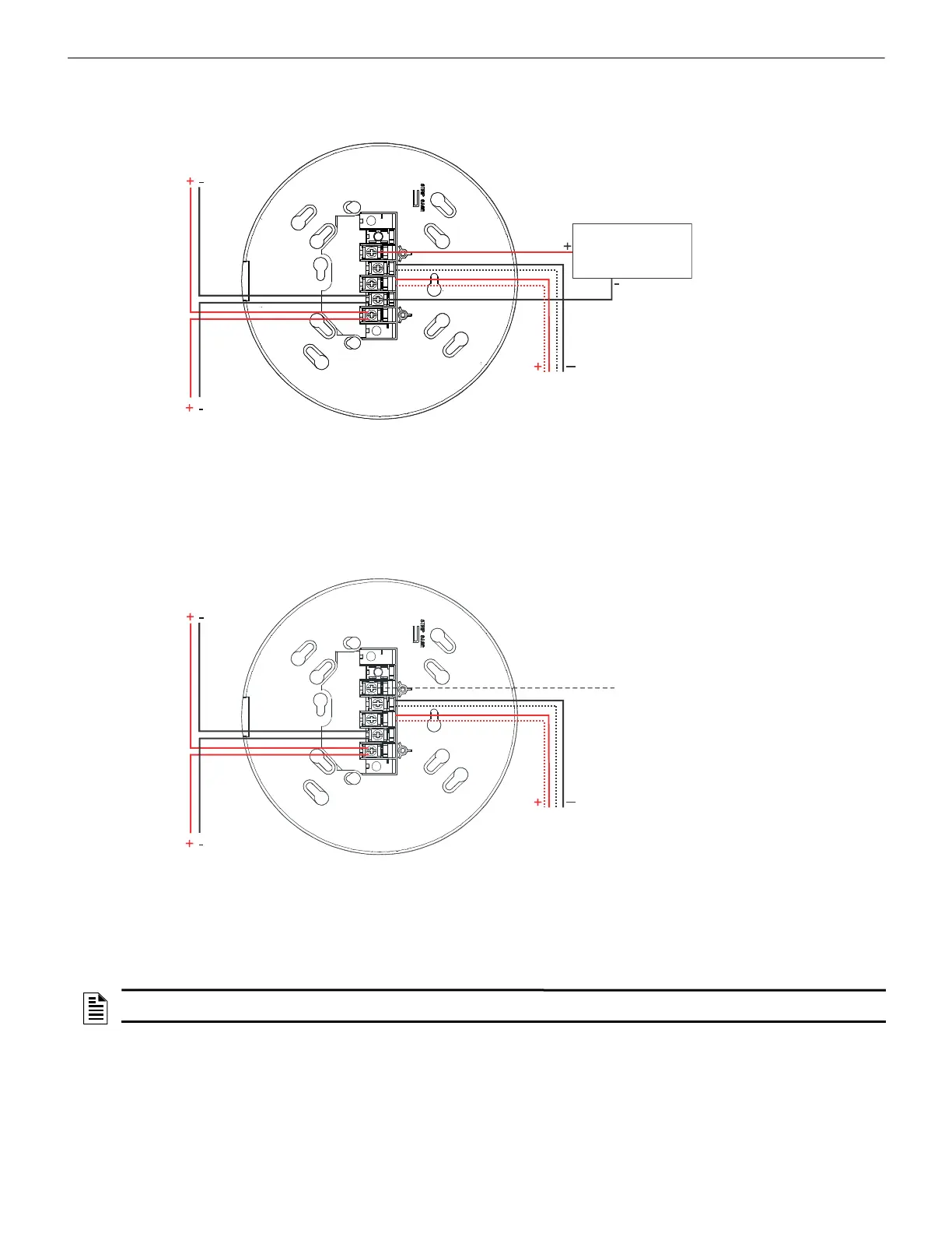
10.5 Wiring a Sounder Base
Figure 10.5 shows typical wiring of the B200S and B200S-LF Sounder Bases.
Figure 10.6 shows typical wiring of the B200SR and B200SR-LF Sounder Base.
Figure 10.5 Wiring of the B200S/B200S-LF Sounder Base
s
l
c
-
b
2
0
0
s
r
w
i
r
e
2
0
1
4
.
w
m
f
To next device
on SLC
SLC
Note: The “grid” pattern on the B200S/B200S-LF
has been removed for illustration purposes only.
Optional Remote
LED Annunciator
RA100Z/400Z
UL-Listed 24VDC Power Supply with System
Sensor sync output. Return for Class A*. See
Appendix A for power supervision.
*When using 24V constant power (AUX power),
additional power supervision relays and modules will
be required to provide supervision when the sounder
bases are inactive.
Figure 10.6 Wiring of the B200SR/B200SR Sounder Base
s
l
c
-
B
2
0
0
S
R
w
i
r
e
2
0
1
4
-
U
L
1
0
.
w
m
f
To next device
on SLC
SLC
Note: The “grid” pattern on the B200SR/B200SR-LF
has been removed for illustration purposes only.
Optional Sounder
Interconnect
UL-Listed 24V Power Supply with System
Sensor sync output. Return for Class A*. See
Appendix A for power supervision.
*When using 24VDC constant power (AUX power),
additional power supervision relays and modules will
be required to provide supervision when the sounder
bases are inactive.
NOTE: The base wiring is identical for color variations. For more detailed wiring on sounder bases, refer to the device’s installation
instructions.

 Loading...


