64 Notifier SLC Wiring Manual — P/N 51253:U9 12/3/2021
Intelligent Detectors, Intelligent Detector Bases, and Wireless Gateway Power Connections: Powered by the SLC
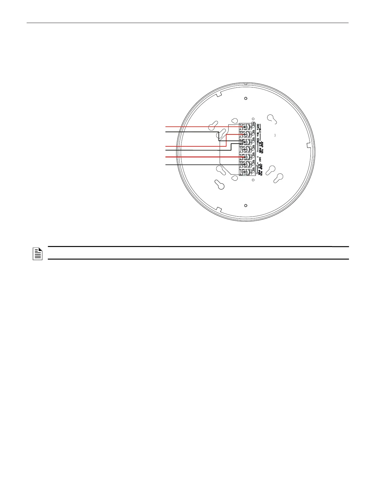
10.8.1 Power Connections: External, Regulated +24 VDC Power Source
The FWSG(A) provides isolation of short circuits of the SLC in Class A installations. SLC connections are power-limited by the panel.
+24VDC must be power-limited by the source. Figure 10.15 shows typical wiring of a Wireless Network Gateway connected to an SLC
when power is supplied by an external, regulated 24 VDC power supply, UL-listed for fire protective service.
For specifics of UL 10th Edition power-supervision requirements, refer to the SWIFT Gateway Manual.
2
.
6
.
w
m
f
Figure 10.15 FWSG(A) Wiring Diagram, Powered by External 24 VDC Power Source
External +24VDC Power
SLC in from FACP/device
SLC out to next device (Class B)
or SLC back to FACP (Class A)
A7
A6
A5
NOTE: Terminal A5 is referenced more than once in the above connections. It is recommended to use wire of the same gauge for all
connections to A5 and use the same wire gauge if there are multiple connections to the same terminal.

 Loading...


