Notifier SLC Wiring Manual — P/N 51253:U9 12/3/2021 39
NFPA Class B IDC Using Monitor Modules Monitor Modules
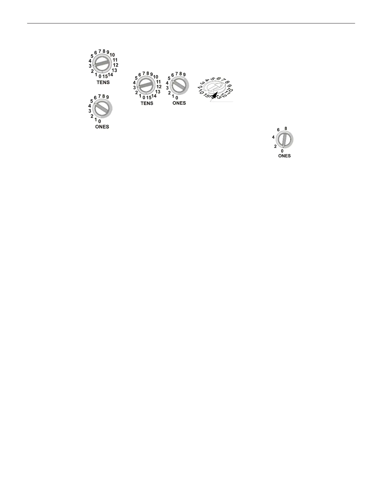
To set an SLC address, use a common screwdriver to adjust the rotary switches on the module to the desired address. The unit shown in
Figure 6.5 is set at address “35”. When finished, mark the address on the module face in the place provided.
6.3 NFPA Class B IDC Using Monitor Modules
Connect the SLC wiring to the module terminals 1 (–) and 2 (+). Each FMM-1 module takes one address on the SLC. Use the rotary
switches on the module to set it to the required SLC address.
Figure 6.6 shows typical wiring for a supervised and power-limited NFPA Class B Initiating Device Circuit using the FMM-1 monitor
module.
Module installation notes:
1. The Initiating Device Circuit (IDC) is supervised and current-limited to 210 microamps @ 24 VDC (nominal).
2. The IDC provides the following services (do not mix):
• Fire alarm service
• Automatic and manual waterflow alarm service with normally open contact devices
• Sprinkler supervisory service with normally open contact devices
• Security service
3. Refer to the Device Compatibility Document for compatible smoke detectors.
4. See Appendix A, “Power Considerations”, on page 66 for information on supervising 24 VDC power.
Type H Rotary
Switches
Breakaway Tab - Modules come
with a raised breakaway tab on the
TENS rotary switch. This tab must
be removed when the module is on
an FACP that uses more than 99
addresses.
SLC-setadd.cdr,SLC-setaddtpH.wmf, SLCbrktabs.wmf
Dual monitor modules: On dual monitor modules, only even
numbers appear on the ONES rotary switch. The module takes
both the selected address and the next-higher address.
Type V Rotary
Switches
Figure 6.5 Setting the SLC Address on Modules

 Loading...


