Notifier SLC Wiring Manual — P/N 51253:U9 12/3/2021 17
SLC Capacity Introduction
1.6.12 ACPS-2406 Addressable Charger/Power Supply
The ACPS-2406 is an auxiliary power supply and battery charger. Each of its four Notification Appliance Circuits (NAC) is individually
addressable, eliminating the need for control modules. In addition, each circuit can provide notification appliance synchronization.
FlashScan and CLIP capable. This product has been discontinued.
1.6.13 AMPS-24 Addressable Power Supply
The AMPS-24 is a primary power supply and battery charger. Depending on its configuration, it can occupy either one or four addresses
on an SLC. FlashScan capable.
1.6.14 PMB-AUX Addressable Charger/Power Supply
PMB-AUX is an addressable primary power supply and battery charger for N16. Each unit supports up to 5 SLM-318 SLC loop cards
and provides four (4) Notification Appliance Circuits (NAC). NACs can provide notification appliance synchronization. FlashScan and
CLIP capable.
1.7 SLC Capacity
The protocol selected for an SLC loop determines the maximum number of devices that can be handled by the loop (see Section 1.5,
“Polling Protocols”, on page 13). Within those limits, the individual control panel may have additional restrictions. See the specific
installation manual for this information.
1.8 SLC Performance
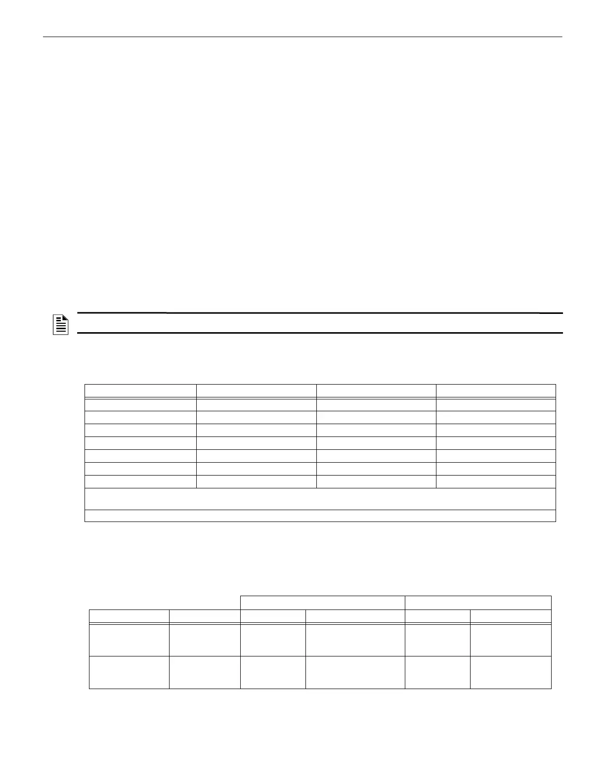
SLC performance (Class B, Class A, or Class X) depends on the configuration of the circuit, the components on the circuit (see
Table 1.3), and the power supply if required for auxiliary power (see individual wiring diagrams). SLC operation meeting Class X
requirements isolates each addressable device on the SLC from faults that may occur on the SLC.
Wiring class requirements are determined by national and local codes. Consult with the Authority Having Jurisdiction before wiring the
SLC. The table below (derived from NFPA 72-2002 and NFPA 72-2013) lists the trouble conditions that result when a fault exists on an
SLC. Items with asterisks are not applicable to NFPA 72-2013. Additional information is broken out in Section 2, “Wiring Require-
ments”, on page 19, and Section 3, “Shielded Wire Termination”, on page 26.
1.9 LED Operation
The table below lists the LED operation on the various devices of an SLC in CLIP (Classic Loop Interface Protocol) Mode and FlashS-
can® Mode. When switching from FlashScan® to CLIP mode, the loop circuit must be powered down for at least 30 seconds to reset
devices to CLIP mode LED operation.
NOTE: NFPA class configuration must be programmed into N16 Series panels. The panel will check that the physical wiring matches and
generate a trouble message if there is a mismatch. See panel documentation for details.
Type of Fault Class B Class A Class X
Single Open Trouble Alarm, Trouble Alarm, Trouble
Single Ground Alarm, Trouble (ground) Alarm, Trouble (ground) Alarm, Trouble (ground)
Short Trouble Trouble Alarm, Trouble
Short and open* Trouble* Trouble* Trouble*
Short and ground* Trouble* Trouble* Alarm*, Trouble*
Open and ground Trouble* Alarm*, Trouble* Alarm, Trouble
Communications loss Trouble Trouble Trouble
• Trouble - The control panel will indicate a trouble condition for this type of fault.
• Alarm - The control panel must be able to process an alarm input signal in the presence of this type of fault.
*Removed from NFPA 72-2013; included for legacy support under NFPA 72-2002 only.
Table 1.3 SLC Circuit Configuration and Performance: Class B, Class A, Class X
CLIP Mode FlashScan® Mode
Control Panel Device Standby Activated Standby Activated
AM2020
AFP1010
Monitor Module
Control Module
Detector
Blinks RED
Blinks GREEN
Blinks RED
RED continuous
2 sec. GREEN, then OFF
RED continuous
N/A
N/A
N/A
N/A
N/A
N/A
AFP-300/AFP-400 Monitor Module
Control Module
Detector
Blinks RED
Blinks GREEN
Blinks RED
RED continuous
GREEN continous
RED continuous
N/A
N/A
N/A
N/A
N/A
N/A
Table 1.4 LED Operations

 Loading...


