Notifier SLC Wiring Manual — P/N 51253:U9 12/3/2021 45
Wiring a Class B NAC (Two-Wire) with Addressable Control Modules Control Modules
7.2.1 Wiring a Solenoid with the FCM-1-REL
(For use with NFS2-3030, NFS2-640, NFS-320(C), and NFS-320SYS.) Figure 7.3 shows the connections to wire the FCM-1-REL to a
solenoid. For UL 864 10th edition applications requiring a manual disconnect switch on the releasing device, see Section 7.5, “Connect-
ing a Releasing Device to the Addressable Control Module”.
7.3 Wiring a Class B NAC (Two-Wire) with Addressable Control Modules
Figure 7.4 depicts a supervised and power-limited NFPA Class B Notification Appliance Circuit (NAC) using the FCM-1 module. In the
sample wiring drawing below, polarized alarm notification appliances are shown connected to the module in a two-wire configuration.
1. See Appendix A, “Power Considerations”, on page 66 for information on monitoring 24 VDC power.
2. Each module can control 2 amps of resistive load (on electronic devices) or 1 amp of inductive load (on mechanical bells and
horns).
3. A power supervision relay is required only on the last module of the power run unless:
• using the no-relay alternative wire method; see Figure A.2, “Alternate: 2-Address Method of Supervising a 24 VDC Circuit -
Class B”.
• using a panel with FlashScan type IDs that provide built-in power supervision. Refer to the panel’s installation documentation
for a list of type codes.
4. Do not T-tap or branch a Class B circuit.
5. Terminate the circuit across the last device using a UL-listed End-of-Line Resistor 47K, 1/2-watt, SSD P/N A2143-00 (ELR-47K in
Canada).
6. Do not loop wiring under the screw terminals of any notification appliance. To maintain supervision, break the wire run at each
device.
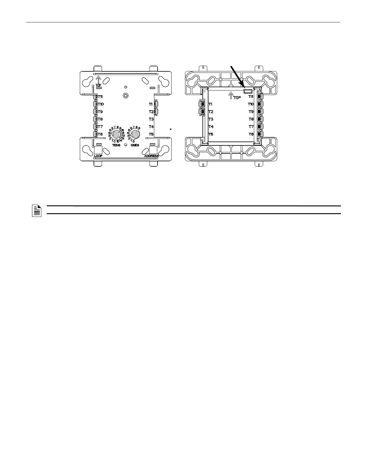
Figure 7.3 FCM-1-REL Wiring Locations and Rear View - Jumper Location
SLC (-)
SLC (+)
24 VDC (-)
24 VDC (+)
Solenoid A (-)
Solenoid A (+)
Solenoid B/A (+)
Solenoid B/A (-)
FCM-1-REL
Wiring Connections
When using the
FCM-1-REL for
Class B
applications,
remove jumper J1.
FCM-1-REL
Rear View - Jumper Location
f
c
m
-
1
-
r
e
l
.
w
m
f
,
f
c
m
-
1
-
r
e
l
_
b
a
c
k
.
w
m
f
NOTE: FlashScan mode only: The FCM-1-REL will not function on an SLC loop that is programmed for CLIP mode.

 Loading...


