Notifier SLC Wiring Manual — P/N 51253:U9 12/3/2021 31
Isolator Detector Bases SLC Circuits with Isolators
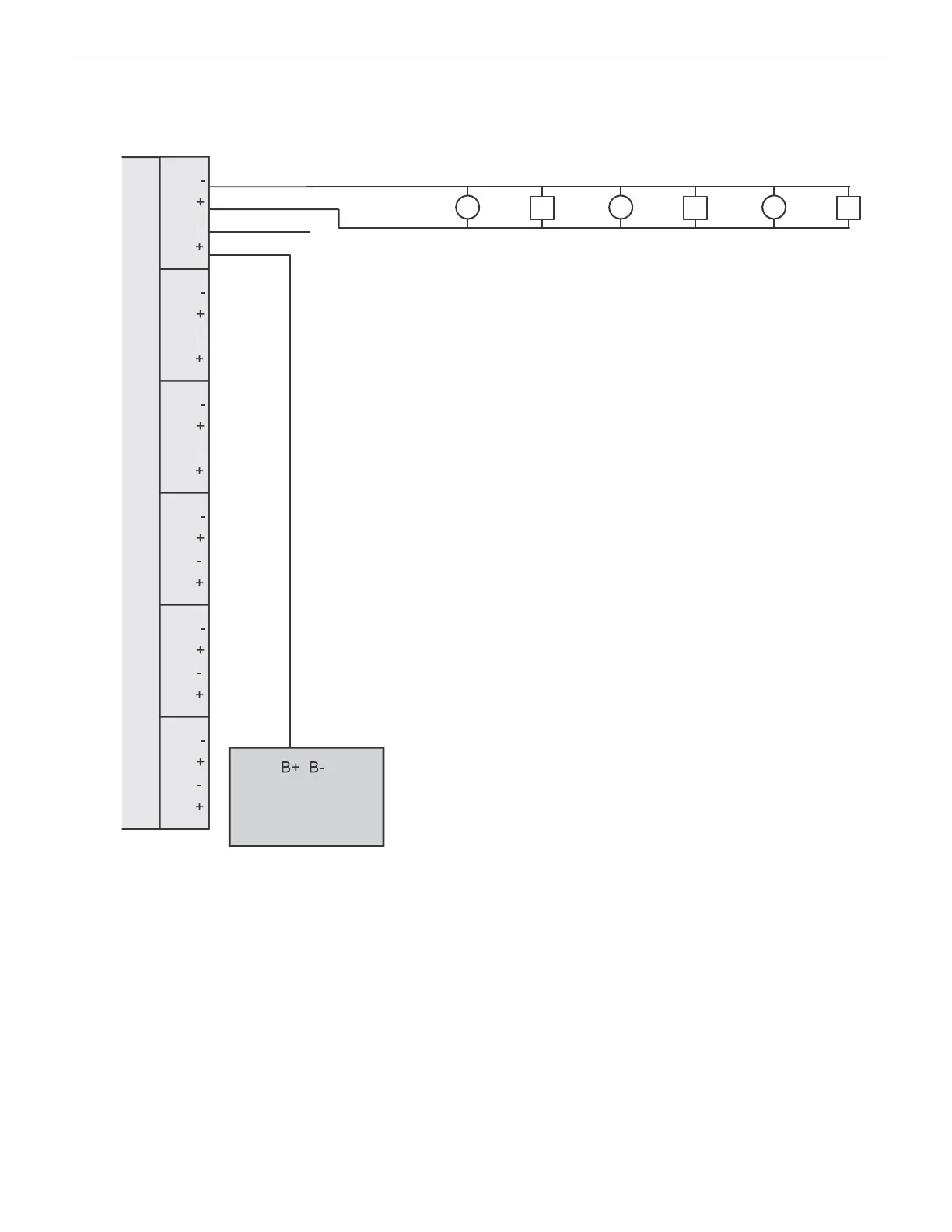
Each of the ISO-6’s six isolator terminals acts as a single ISO-X module. Figure 5.2 shows a Class B example for wiring the ISO-6. Ter-
minal numbers are added for clarification; these do not appear on the physical device.
5.3 Isolator Detector Bases
Isolator detector bases prevent an entire communications loop from being disabled when a short circuit occurs. This is accomplished by
isolating that part of the loop containing the short from the remainder of the circuit. These bases also automatically restore the entire loop
when the cause of the short circuit is corrected.
B224BI-WH/B224BI-IV is an intelligent isolator base used with FlashScan
®
detectors and most CLIP mode detectors. (An older version
B224BI had fewer color options.)
5.3.1 How an Isolator Base Works
If a short circuit fault occurs at point “X”, devices A, B, C & detector 2 will cease to function and display a trouble warning at the control
panel. Devices D, E, F & detectors 1, 3, 4, and 5 will remain normal as they are served by ‘SLC Return’.
Isolator 1Isolator 2Isolator 3Isolator 4Isolator 5Isolator 6
Out -
Out +
In -
In +
SLC-ISO-6.wmf
SLC Loop
ISO-6
Six Fault
Isolator
Module
Fire Alarm Control Panel
Figure 5.2 Wiring the ISO-6 Six Fault Isolator Module

 Loading...


