32 Notifier SLC Wiring Manual — P/N 51253:U9 12/3/2021
SLC Circuits with Isolators Isolator Detector Bases
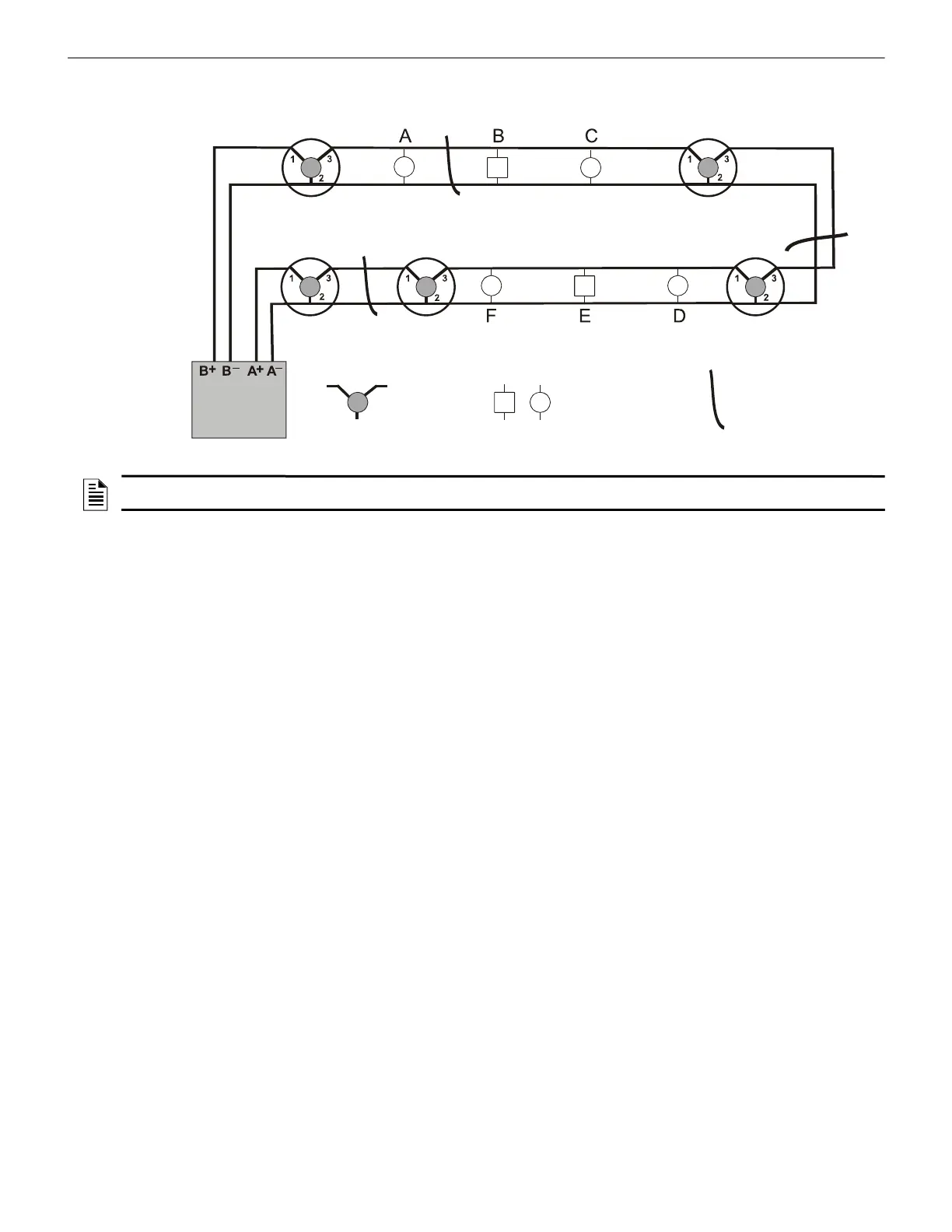
If a short circuit fault occurs at point “Y”, all devices will continue to function. If a short circuit fault occurs at point “Z”, only detector
4 will cease to function.
Non-Isolating DeviceIsolator Base
X
Z
Control Panel
SLC Return
SLC Out
SLC-isowork.wmf
Detector 1
Detector 2
Detector 3
Detector 4
Detector 5
Y
Short-circuit path
Figure 5.3 Isolator Base Circuit: Sample Class A Wiring
NOTE: For information on wiring an isolator base, refer to Figure 10.3, “Wiring a B224BI-WH/B224BI-IV Isolator Base Mounting Plate” on
page 56.

 Loading...


