56 Notifier SLC Wiring Manual — P/N 51253:U9 12/3/2021
Intelligent Detectors, Intelligent Detector Bases, and Wireless Gateway Wiring an Isolator Base
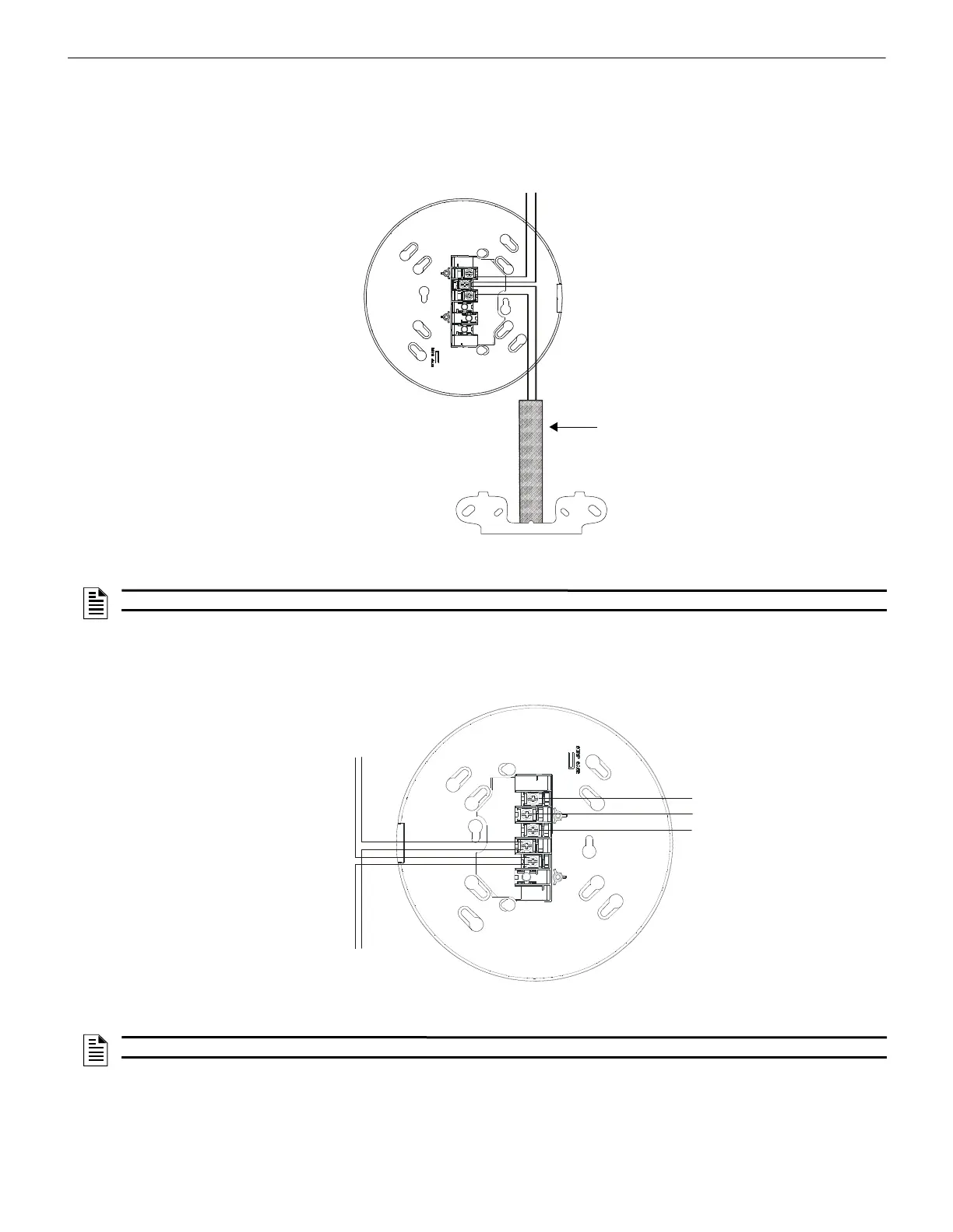
10.3 Wiring an Isolator Base
The Isolator base will isolate its detector from short circuits that occur on the SLC connected at terminals 3 and 2. It will not isolate its
installed detector from short circuits that occur on the SLC connected at terminals 1 and 2. In Class X applications, the loss of a single
detector during a short circuit is not acceptable, and an isolator module must be installed as shown in the figure below.
10.4 Wiring a Relay Base
Figure 10.4 shows typical wiring of the B224RB plug-in relay detector base connected to an SLC.
SLC Out
SLC In
Conduit
ISO-X Isolator Module
s
l
c
-
2
2
4
b
i
2
w
i
r
e
.
w
m
f
Figure 10.3 Wiring a B224BI-WH/B224BI-IV Isolator Base Mounting Plate
Note: The “grid” pattern on
the redesigned B224BI
Series mounting plate has
been removed for
illustration purposes only.
NOTE: The base wiring is identical for color variations.
s
l
c
-
b
2
2
4
r
b
2
w
i
r
e
.
w
m
f
Figure 10.4 Wiring of a B224RB Relay Base Mounting Plate
To next device
on SLC
SLC
Normally Closed
Common
Normally Open
Note: The “grid” pattern on the
redesigned B224RB mounting
plate has been removed for
illustration purposes only.
NOTE: The base wiring is identical for color variations.

 Loading...


