54 Notifier SLC Wiring Manual — P/N 51253:U9 12/3/2021
Intelligent Detectors, Intelligent Detector Bases, and Wireless Gateway Wiring a Detector Base
10.1.3 Wireless Gateway
The FWSG(A) Wireless Gateway acts as a bridge between a group of wireless fire devices, and a FlashScan SLC loop on N16, NFS-320,
NFS-320SYS, NFS2-640, and NFS2-3030 (version 22 and above). The gateway can be powered by the SLC loop or by an external 24
VDC, UL-listed power supply. See Section 10.7.
For details about the wireless network itself, see the SWIFT® Wireless Gateway Manual.
10.2 Wiring a Detector Base
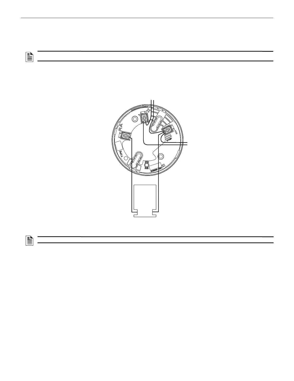
Figure 10.1 shows typical wiring of a standard detector base (B501 is shown) connected to an SLC. An optional RA100Z Remote LED
Annunciator is shown connected to the base.
NOTE: When a wireless relay is in use, modules device count must be limited to 109 modules per loop. This includes wired and wireless
modules that are on the same loop. The module address range must be within 1-109.
S
L
C
-
B
5
0
1
w
i
r
e
.
w
m
f
RA100Z
Remote LED
Annunciator
(Optional)
Figure 10.1 Wiring Detector Base B300-6/-IV, B210LP, or B501
To Next
Device on
SLC
From Control Panel SLC
NOTE: The base wiring is identical for the flanged B300-6, B210LP, flangeless B501, and color variations.

 Loading...


